
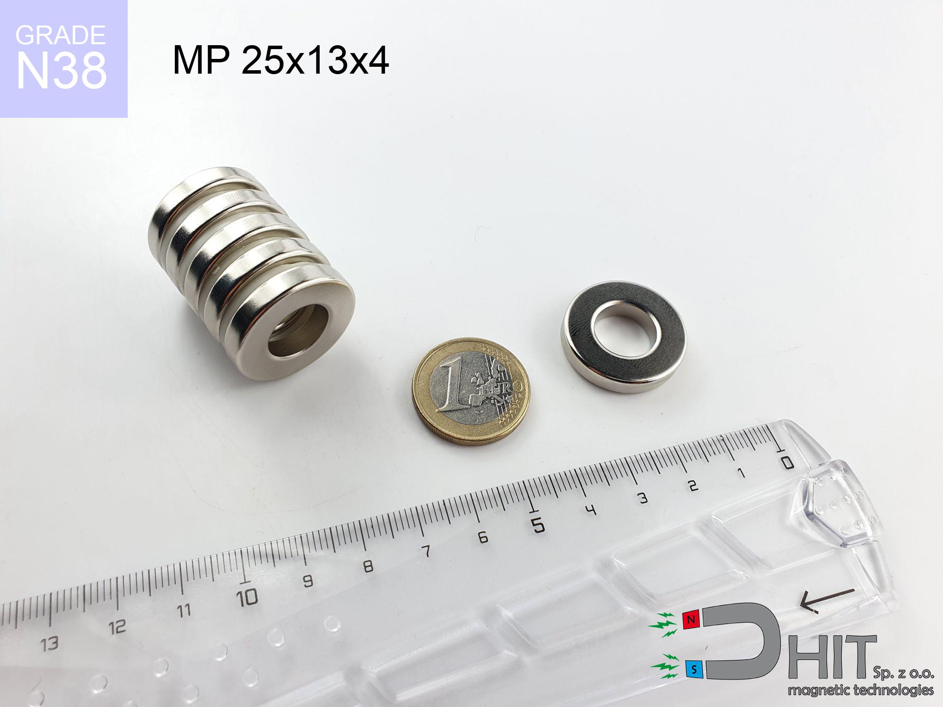
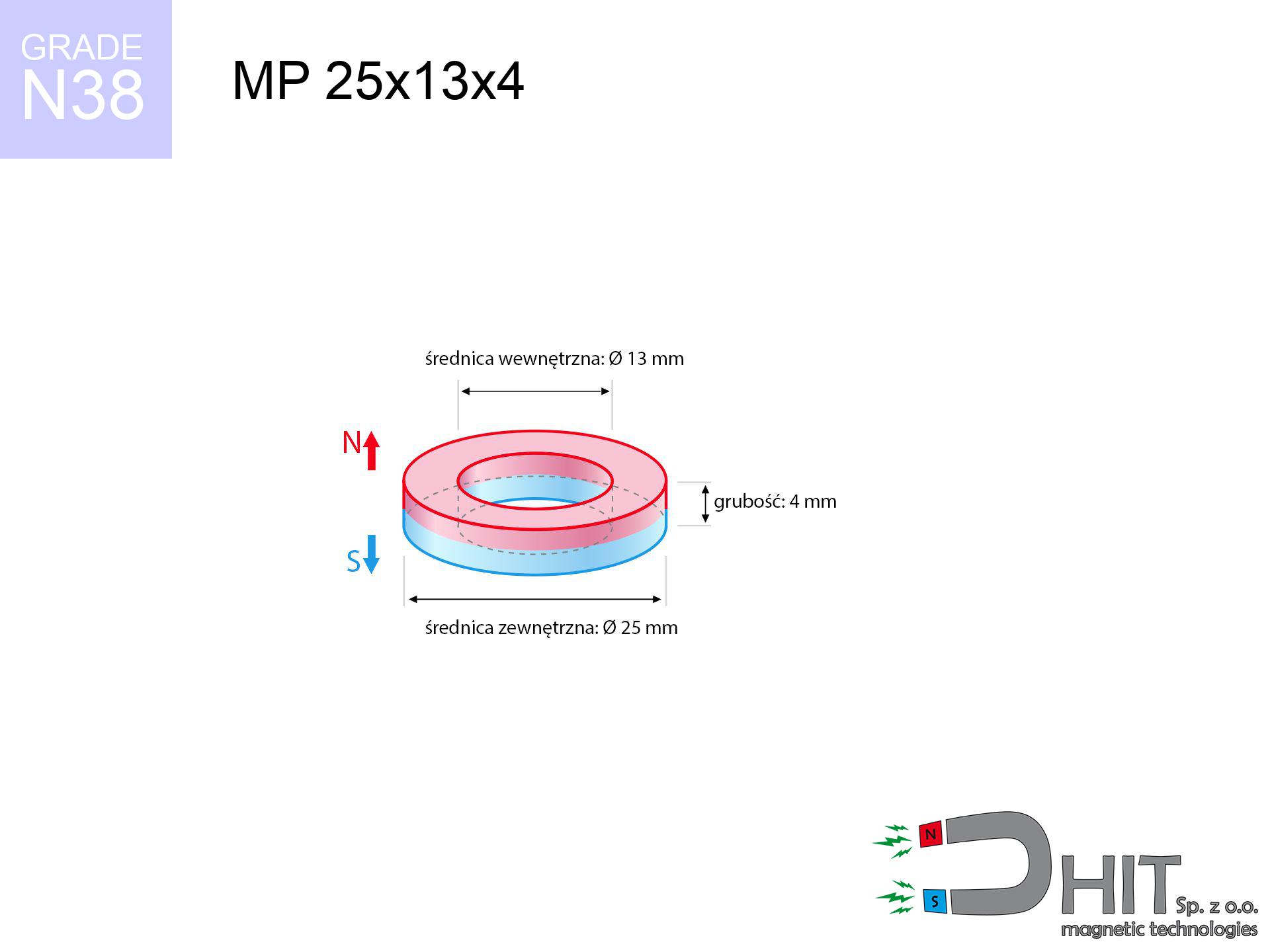
MP 25x13x4 / N38 - ring magnet
ring magnet
Catalog no 030190
GTIN/EAN: 5906301812074
Diameter
25 mm [±0,1 mm]
internal diameter Ø
13 mm [±0,1 mm]
Height
4 mm [±0,1 mm]
Weight
10.74 g
Magnetization Direction
↑ axial
Load capacity
4.14 kg / 40.57 N
Magnetic Induction
188.92 mT / 1889 Gs
Coating
[NiCuNi] Nickel
6.77 ZŁ with VAT / pcs + price for transport
5.50 ZŁ net + 23% VAT / pcs
bulk discounts:
Need more?
Call us now
+48 22 499 98 98
if you prefer drop us a message via
contact form
through our site.
Strength along with appearance of a neodymium magnet can be verified on our
power calculator.
Order by 14:00 and we’ll ship today!
Technical parameters of the product - MP 25x13x4 / N38 - ring magnet
Specification / characteristics - MP 25x13x4 / N38 - ring magnet
| properties | values |
|---|---|
| Cat. no. | 030190 |
| GTIN/EAN | 5906301812074 |
| Production/Distribution | Dhit sp. z o.o. |
| Country of origin | Poland / China / Germany |
| Customs code | 85059029 |
| Diameter | 25 mm [±0,1 mm] |
| internal diameter Ø | 13 mm [±0,1 mm] |
| Height | 4 mm [±0,1 mm] |
| Weight | 10.74 g |
| Magnetization Direction | ↑ axial |
| Load capacity ~ ? | 4.14 kg / 40.57 N |
| Magnetic Induction ~ ? | 188.92 mT / 1889 Gs |
| Coating | [NiCuNi] Nickel |
| Manufacturing Tolerance | ±0.1 mm |
Magnetic properties of material N38
| properties | values | units |
|---|---|---|
| remenance Br [min. - max.] ? | 12.2-12.6 | kGs |
| remenance Br [min. - max.] ? | 1220-1260 | mT |
| coercivity bHc ? | 10.8-11.5 | kOe |
| coercivity bHc ? | 860-915 | kA/m |
| actual internal force iHc | ≥ 12 | kOe |
| actual internal force iHc | ≥ 955 | kA/m |
| energy density [min. - max.] ? | 36-38 | BH max MGOe |
| energy density [min. - max.] ? | 287-303 | BH max KJ/m |
| max. temperature ? | ≤ 80 | °C |
Physical properties of sintered neodymium magnets Nd2Fe14B at 20°C
| properties | values | units |
|---|---|---|
| Vickers hardness | ≥550 | Hv |
| Density | ≥7.4 | g/cm3 |
| Curie Temperature TC | 312 - 380 | °C |
| Curie Temperature TF | 593 - 716 | °F |
| Specific resistance | 150 | μΩ⋅cm |
| Bending strength | 250 | MPa |
| Compressive strength | 1000~1100 | MPa |
| Thermal expansion parallel (∥) to orientation (M) | (3-4) x 10-6 | °C-1 |
| Thermal expansion perpendicular (⊥) to orientation (M) | -(1-3) x 10-6 | °C-1 |
| Young's modulus | 1.7 x 10⁴ | kg/mm² |
Engineering simulation of the assembly - data
The following information represent the outcome of a mathematical analysis. Results rely on models for the material Nd2Fe14B. Real-world parameters may differ. Use these calculations as a preliminary roadmap for designers.
Table 1: Static pull force (force vs distance) - characteristics
MP 25x13x4 / N38
| Distance (mm) | Induction (Gauss) / mT | Pull Force (kg/lbs/g/N) | Risk Status |
|---|---|---|---|
| 0 mm |
5777 Gs
577.7 mT
|
4.14 kg / 9.13 lbs
4140.0 g / 40.6 N
|
warning |
| 1 mm |
5310 Gs
531.0 mT
|
3.50 kg / 7.71 lbs
3497.4 g / 34.3 N
|
warning |
| 2 mm |
4846 Gs
484.6 mT
|
2.91 kg / 6.42 lbs
2912.4 g / 28.6 N
|
warning |
| 3 mm |
4397 Gs
439.7 mT
|
2.40 kg / 5.29 lbs
2398.5 g / 23.5 N
|
warning |
| 5 mm |
3576 Gs
357.6 mT
|
1.59 kg / 3.50 lbs
1586.2 g / 15.6 N
|
safe |
| 10 mm |
2073 Gs
207.3 mT
|
0.53 kg / 1.17 lbs
532.9 g / 5.2 N
|
safe |
| 15 mm |
1231 Gs
123.1 mT
|
0.19 kg / 0.41 lbs
188.0 g / 1.8 N
|
safe |
| 20 mm |
773 Gs
77.3 mT
|
0.07 kg / 0.16 lbs
74.0 g / 0.7 N
|
safe |
| 30 mm |
356 Gs
35.6 mT
|
0.02 kg / 0.03 lbs
15.7 g / 0.2 N
|
safe |
| 50 mm |
115 Gs
11.5 mT
|
0.00 kg / 0.00 lbs
1.6 g / 0.0 N
|
safe |
Table 2: Vertical hold (vertical surface)
MP 25x13x4 / N38
| Distance (mm) | Friction coefficient | Pull Force (kg/lbs/g/N) |
|---|---|---|
| 0 mm | Stal (~0.2) |
0.83 kg / 1.83 lbs
828.0 g / 8.1 N
|
| 1 mm | Stal (~0.2) |
0.70 kg / 1.54 lbs
700.0 g / 6.9 N
|
| 2 mm | Stal (~0.2) |
0.58 kg / 1.28 lbs
582.0 g / 5.7 N
|
| 3 mm | Stal (~0.2) |
0.48 kg / 1.06 lbs
480.0 g / 4.7 N
|
| 5 mm | Stal (~0.2) |
0.32 kg / 0.70 lbs
318.0 g / 3.1 N
|
| 10 mm | Stal (~0.2) |
0.11 kg / 0.23 lbs
106.0 g / 1.0 N
|
| 15 mm | Stal (~0.2) |
0.04 kg / 0.08 lbs
38.0 g / 0.4 N
|
| 20 mm | Stal (~0.2) |
0.01 kg / 0.03 lbs
14.0 g / 0.1 N
|
| 30 mm | Stal (~0.2) |
0.00 kg / 0.01 lbs
4.0 g / 0.0 N
|
| 50 mm | Stal (~0.2) |
0.00 kg / 0.00 lbs
0.0 g / 0.0 N
|
Table 3: Wall mounting (sliding) - behavior on slippery surfaces
MP 25x13x4 / N38
| Surface type | Friction coefficient / % Mocy | Max load (kg/lbs/g/N) |
|---|---|---|
| Raw steel |
µ = 0.3
30% Nominalnej Siły
|
1.24 kg / 2.74 lbs
1242.0 g / 12.2 N
|
| Painted steel (standard) |
µ = 0.2
20% Nominalnej Siły
|
0.83 kg / 1.83 lbs
828.0 g / 8.1 N
|
| Oily/slippery steel |
µ = 0.1
10% Nominalnej Siły
|
0.41 kg / 0.91 lbs
414.0 g / 4.1 N
|
| Magnet with anti-slip rubber |
µ = 0.5
50% Nominalnej Siły
|
2.07 kg / 4.56 lbs
2070.0 g / 20.3 N
|
Table 4: Material efficiency (saturation) - power losses
MP 25x13x4 / N38
| Steel thickness (mm) | % power | Real pull force (kg/lbs/g/N) |
|---|---|---|
| 0.5 mm |
|
0.41 kg / 0.91 lbs
414.0 g / 4.1 N
|
| 1 mm |
|
1.04 kg / 2.28 lbs
1035.0 g / 10.2 N
|
| 2 mm |
|
2.07 kg / 4.56 lbs
2070.0 g / 20.3 N
|
| 3 mm |
|
3.10 kg / 6.85 lbs
3105.0 g / 30.5 N
|
| 5 mm |
|
4.14 kg / 9.13 lbs
4140.0 g / 40.6 N
|
| 10 mm |
|
4.14 kg / 9.13 lbs
4140.0 g / 40.6 N
|
| 11 mm |
|
4.14 kg / 9.13 lbs
4140.0 g / 40.6 N
|
| 12 mm |
|
4.14 kg / 9.13 lbs
4140.0 g / 40.6 N
|
Table 5: Working in heat (stability) - resistance threshold
MP 25x13x4 / N38
| Ambient temp. (°C) | Power loss | Remaining pull (kg/lbs/g/N) | Status |
|---|---|---|---|
| 20 °C | 0.0% |
4.14 kg / 9.13 lbs
4140.0 g / 40.6 N
|
OK |
| 40 °C | -2.2% |
4.05 kg / 8.93 lbs
4048.9 g / 39.7 N
|
OK |
| 60 °C | -4.4% |
3.96 kg / 8.73 lbs
3957.8 g / 38.8 N
|
OK |
| 80 °C | -6.6% |
3.87 kg / 8.52 lbs
3866.8 g / 37.9 N
|
|
| 100 °C | -28.8% |
2.95 kg / 6.50 lbs
2947.7 g / 28.9 N
|
Table 6: Two magnets (attraction) - forces in the system
MP 25x13x4 / N38
| Gap (mm) | Attraction (kg/lbs) (N-S) | Shear Force (kg/lbs/g/N) | Repulsion (kg/lbs) (N-N) |
|---|---|---|---|
| 0 mm |
83.66 kg / 184.44 lbs
6 082 Gs
|
12.55 kg / 27.67 lbs
12549 g / 123.1 N
|
N/A |
| 1 mm |
77.09 kg / 169.95 lbs
11 091 Gs
|
11.56 kg / 25.49 lbs
11563 g / 113.4 N
|
69.38 kg / 152.95 lbs
~0 Gs
|
| 2 mm |
70.68 kg / 155.81 lbs
10 620 Gs
|
10.60 kg / 23.37 lbs
10601 g / 104.0 N
|
63.61 kg / 140.23 lbs
~0 Gs
|
| 3 mm |
64.59 kg / 142.40 lbs
10 153 Gs
|
9.69 kg / 21.36 lbs
9689 g / 95.0 N
|
58.13 kg / 128.16 lbs
~0 Gs
|
| 5 mm |
53.48 kg / 117.90 lbs
9 238 Gs
|
8.02 kg / 17.68 lbs
8022 g / 78.7 N
|
48.13 kg / 106.11 lbs
~0 Gs
|
| 10 mm |
32.05 kg / 70.66 lbs
7 152 Gs
|
4.81 kg / 10.60 lbs
4808 g / 47.2 N
|
28.85 kg / 63.60 lbs
~0 Gs
|
| 20 mm |
10.77 kg / 23.74 lbs
4 145 Gs
|
1.62 kg / 3.56 lbs
1615 g / 15.8 N
|
9.69 kg / 21.37 lbs
~0 Gs
|
| 50 mm |
0.66 kg / 1.45 lbs
1 024 Gs
|
0.10 kg / 0.22 lbs
99 g / 1.0 N
|
0.59 kg / 1.30 lbs
~0 Gs
|
| 60 mm |
0.32 kg / 0.70 lbs
712 Gs
|
0.05 kg / 0.10 lbs
48 g / 0.5 N
|
0.29 kg / 0.63 lbs
~0 Gs
|
| 70 mm |
0.17 kg / 0.36 lbs
514 Gs
|
0.02 kg / 0.05 lbs
25 g / 0.2 N
|
0.15 kg / 0.33 lbs
~0 Gs
|
| 80 mm |
0.09 kg / 0.20 lbs
383 Gs
|
0.01 kg / 0.03 lbs
14 g / 0.1 N
|
0.08 kg / 0.18 lbs
~0 Gs
|
| 90 mm |
0.05 kg / 0.12 lbs
293 Gs
|
0.01 kg / 0.02 lbs
8 g / 0.1 N
|
0.05 kg / 0.11 lbs
~0 Gs
|
| 100 mm |
0.03 kg / 0.07 lbs
230 Gs
|
0.00 kg / 0.01 lbs
5 g / 0.0 N
|
0.03 kg / 0.07 lbs
~0 Gs
|
Table 7: Hazards (implants) - warnings
MP 25x13x4 / N38
| Object / Device | Limit (Gauss) / mT | Safe distance |
|---|---|---|
| Pacemaker | 5 Gs (0.5 mT) | 17.0 cm |
| Hearing aid | 10 Gs (1.0 mT) | 13.5 cm |
| Mechanical watch | 20 Gs (2.0 mT) | 10.5 cm |
| Mobile device | 40 Gs (4.0 mT) | 8.0 cm |
| Car key | 50 Gs (5.0 mT) | 7.5 cm |
| Payment card | 400 Gs (40.0 mT) | 3.0 cm |
| HDD hard drive | 600 Gs (60.0 mT) | 2.5 cm |
Table 8: Impact energy (kinetic energy) - warning
MP 25x13x4 / N38
| Start from (mm) | Speed (km/h) | Energy (J) | Predicted outcome |
|---|---|---|---|
| 10 mm |
21.33 km/h
(5.93 m/s)
|
0.19 J | |
| 30 mm |
34.38 km/h
(9.55 m/s)
|
0.49 J | |
| 50 mm |
44.29 km/h
(12.30 m/s)
|
0.81 J | |
| 100 mm |
62.62 km/h
(17.39 m/s)
|
1.62 J |
Table 9: Surface protection spec
MP 25x13x4 / N38
| Technical parameter | Value / Description |
|---|---|
| Coating type | [NiCuNi] Nickel |
| Layer structure | Nickel - Copper - Nickel |
| Layer thickness | 10-20 µm |
| Salt spray test (SST) ? | 24 h |
| Recommended environment | Indoors only (dry) |
Table 10: Construction data (Flux)
MP 25x13x4 / N38
| Parameter | Value | SI Unit / Description |
|---|---|---|
| Magnetic Flux | 24 861 Mx | 248.6 µWb |
| Pc Coefficient | 1.02 | High (Stable) |
Table 11: Hydrostatics and buoyancy
MP 25x13x4 / N38
| Environment | Effective steel pull | Effect |
|---|---|---|
| Air (land) | 4.14 kg | Standard |
| Water (riverbed) |
4.74 kg
(+0.60 kg buoyancy gain)
|
+14.5% |
1. Wall mount (shear)
*Note: On a vertical surface, the magnet holds only ~20% of its max power.
2. Efficiency vs thickness
*Thin steel (e.g. computer case) severely weakens the holding force.
3. Temperature resistance
*For N38 material, the critical limit is 80°C.
4. Demagnetization curve and operating point (B-H)
chart generated for the permeance coefficient Pc (Permeance Coefficient) = 1.02
The chart above illustrates the magnetic characteristics of the material within the second quadrant of the hysteresis loop. The solid red line represents the demagnetization curve (material potential), while the dashed blue line is the load line based on the magnet's geometry. The Pc (Permeance Coefficient), also known as the load line slope, is a dimensionless value that describes the relationship between the magnet's shape and its magnetic stability. The intersection of these two lines (the black dot) is the operating point — it determines the actual magnetic flux density generated by the magnet in this specific configuration. A higher Pc value means the magnet is more 'slender' (tall relative to its area), resulting in a higher operating point and better resistance to irreversible demagnetization caused by external fields or temperature. A value of 0.42 is relatively low (typical for flat magnets), meaning the operating point is closer to the 'knee' of the curve — caution is advised when operating at temperatures near the maximum limit to avoid strength loss.
Chemical composition
| iron (Fe) | 64% – 68% |
| neodymium (Nd) | 29% – 32% |
| boron (B) | 1.1% – 1.2% |
| dysprosium (Dy) | 0.5% – 2.0% |
| coating (Ni-Cu-Ni) | < 0.05% |
Ecology and recycling (GPSR)
| recyclability (EoL) | 100% |
| recycled raw materials | ~10% (pre-cons) |
| carbon footprint | low / zredukowany |
| waste code (EWC) | 16 02 16 |
Other proposals
![UMGGW 88x8.5 [M6] GW / N38 - magnetic holder rubber internal thread](https://cdn3.dhit.pl/graphics/products/umg-88x8.5-m8-gw-let.jpg "UMGGW 88x8.5 [M6] GW / N38 - magnetic holder rubber internal thread")


Strengths as well as weaknesses of Nd2Fe14B magnets.
Strengths
- They do not lose magnetism, even after around 10 years – the drop in strength is only ~1% (according to tests),
- Magnets very well resist against loss of magnetization caused by ambient magnetic noise,
- Thanks to the reflective finish, the coating of Ni-Cu-Ni, gold-plated, or silver-plated gives an clean appearance,
- Magnets possess exceptionally strong magnetic induction on the outer side,
- Thanks to resistance to high temperature, they are able to function (depending on the shape) even at temperatures up to 230°C and higher...
- In view of the possibility of free shaping and customization to unique projects, NdFeB magnets can be manufactured in a wide range of forms and dimensions, which expands the range of possible applications,
- Fundamental importance in high-tech industry – they are used in mass storage devices, motor assemblies, precision medical tools, also multitasking production systems.
- Compactness – despite small sizes they provide effective action, making them ideal for precision applications
Disadvantages
- Susceptibility to cracking is one of their disadvantages. Upon intense impact they can fracture. We recommend keeping them in a steel housing, which not only protects them against impacts but also raises their durability
- NdFeB magnets demagnetize when exposed to high temperatures. After reaching 80°C, many of them experience permanent weakening of strength (a factor is the shape as well as dimensions of the magnet). We offer magnets specially adapted to work at temperatures up to 230°C marked [AH], which are extremely resistant to heat
- Due to the susceptibility of magnets to corrosion in a humid environment, we advise using waterproof magnets made of rubber, plastic or other material resistant to moisture, when using outdoors
- We recommend a housing - magnetic holder, due to difficulties in producing nuts inside the magnet and complex forms.
- Potential hazard related to microscopic parts of magnets pose a threat, in case of ingestion, which gains importance in the context of child safety. Additionally, small elements of these devices are able to be problematic in diagnostics medical in case of swallowing.
- High unit price – neodymium magnets have a higher price than other types of magnets (e.g. ferrite), which hinders application in large quantities
Holding force characteristics
Maximum lifting force for a neodymium magnet – what affects it?
- using a sheet made of mild steel, acting as a circuit closing element
- with a cross-section no less than 10 mm
- characterized by even structure
- under conditions of gap-free contact (metal-to-metal)
- during pulling in a direction vertical to the plane
- at standard ambient temperature
Practical aspects of lifting capacity – factors
- Distance – the presence of any layer (paint, dirt, air) interrupts the magnetic circuit, which lowers capacity rapidly (even by 50% at 0.5 mm).
- Pull-off angle – remember that the magnet holds strongest perpendicularly. Under shear forces, the holding force drops drastically, often to levels of 20-30% of the nominal value.
- Substrate thickness – for full efficiency, the steel must be adequately massive. Thin sheet restricts the lifting capacity (the magnet "punches through" it).
- Plate material – low-carbon steel gives the best results. Higher carbon content decrease magnetic properties and lifting capacity.
- Plate texture – ground elements guarantee perfect abutment, which improves force. Uneven metal reduce efficiency.
- Thermal factor – hot environment weakens magnetic field. Exceeding the limit temperature can permanently damage the magnet.
Holding force was checked on the plate surface of 20 mm thickness, when a perpendicular force was applied, whereas under attempts to slide the magnet the lifting capacity is smaller. Moreover, even a slight gap between the magnet and the plate reduces the holding force.
Warnings
GPS Danger
GPS units and smartphones are highly susceptible to magnetic fields. Direct contact with a strong magnet can decalibrate the internal compass in your phone.
Nickel coating and allergies
It is widely known that the nickel plating (standard magnet coating) is a potent allergen. If your skin reacts to metals, prevent direct skin contact and opt for coated magnets.
Hand protection
Pinching hazard: The attraction force is so immense that it can cause hematomas, crushing, and broken bones. Protective gloves are recommended.
Danger to pacemakers
Individuals with a pacemaker have to keep an absolute distance from magnets. The magnetism can interfere with the operation of the life-saving device.
Protect data
Do not bring magnets close to a purse, laptop, or TV. The magnetic field can irreversibly ruin these devices and erase data from cards.
Powerful field
Handle with care. Neodymium magnets act from a distance and connect with huge force, often faster than you can react.
Demagnetization risk
Standard neodymium magnets (N-type) lose power when the temperature goes above 80°C. This process is irreversible.
Material brittleness
NdFeB magnets are ceramic materials, which means they are prone to chipping. Clashing of two magnets leads to them shattering into small pieces.
Do not give to children
Always store magnets out of reach of children. Ingestion danger is high, and the consequences of magnets connecting inside the body are life-threatening.
Do not drill into magnets
Drilling and cutting of NdFeB material poses a fire risk. Neodymium dust oxidizes rapidly with oxygen and is hard to extinguish.
Tabela kosztu i czasu dostawy
Płatność przed wysyłką:

GLS kurier
Przesyłka będzie u Ciebie za 2-3 dni
14.99 ZŁ

InPost Paczkomaty 24/7
Przesyłka będzie u Ciebie za 1-2 dni
12.30 ZŁ
Płatność przy odbiorze (pobranie):
GLS kurier
Przesyłka będzie u Ciebie za 1-2 dni
23.00 ZŁ
Rate the product
Your rating