
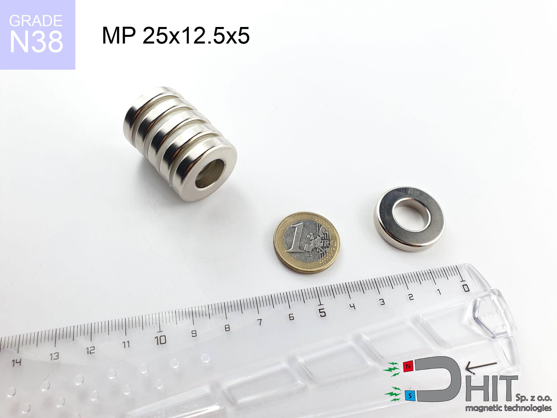
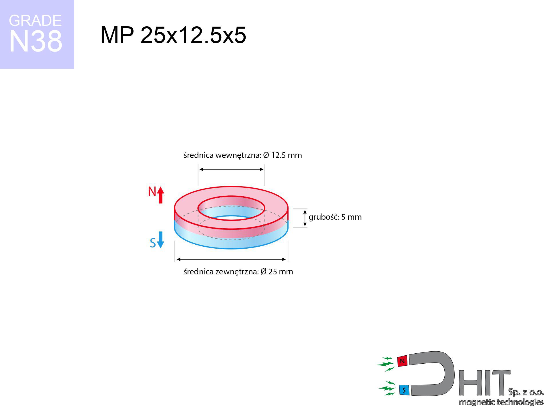
MP 25x12.5x5 / N38 - ring magnet
ring magnet
Catalog no 030342
GTIN/EAN: 5906301812289
Diameter
25 mm [±0,1 mm]
internal diameter Ø
12.5 mm [±0,1 mm]
Height
5 mm [±0,1 mm]
Weight
13.81 g
Magnetization Direction
↑ axial
Load capacity
5.98 kg / 58.64 N
Magnetic Induction
230.20 mT / 2302 Gs
Coating
[NiCuNi] Nickel
6.20 ZŁ with VAT / pcs + price for transport
5.04 ZŁ net + 23% VAT / pcs
bulk discounts:
Need more?
Contact us by phone
+48 22 499 98 98
otherwise drop us a message by means of
request form
the contact section.
Strength along with appearance of a magnet can be calculated on our
power calculator.
Orders submitted before 14:00 will be dispatched today!
Technical specification - MP 25x12.5x5 / N38 - ring magnet
Specification / characteristics - MP 25x12.5x5 / N38 - ring magnet
| properties | values |
|---|---|
| Cat. no. | 030342 |
| GTIN/EAN | 5906301812289 |
| Production/Distribution | Dhit sp. z o.o. |
| Country of origin | Poland / China / Germany |
| Customs code | 85059029 |
| Diameter | 25 mm [±0,1 mm] |
| internal diameter Ø | 12.5 mm [±0,1 mm] |
| Height | 5 mm [±0,1 mm] |
| Weight | 13.81 g |
| Magnetization Direction | ↑ axial |
| Load capacity ~ ? | 5.98 kg / 58.64 N |
| Magnetic Induction ~ ? | 230.20 mT / 2302 Gs |
| Coating | [NiCuNi] Nickel |
| Manufacturing Tolerance | ±0.1 mm |
Magnetic properties of material N38
| properties | values | units |
|---|---|---|
| remenance Br [min. - max.] ? | 12.2-12.6 | kGs |
| remenance Br [min. - max.] ? | 1220-1260 | mT |
| coercivity bHc ? | 10.8-11.5 | kOe |
| coercivity bHc ? | 860-915 | kA/m |
| actual internal force iHc | ≥ 12 | kOe |
| actual internal force iHc | ≥ 955 | kA/m |
| energy density [min. - max.] ? | 36-38 | BH max MGOe |
| energy density [min. - max.] ? | 287-303 | BH max KJ/m |
| max. temperature ? | ≤ 80 | °C |
Physical properties of sintered neodymium magnets Nd2Fe14B at 20°C
| properties | values | units |
|---|---|---|
| Vickers hardness | ≥550 | Hv |
| Density | ≥7.4 | g/cm3 |
| Curie Temperature TC | 312 - 380 | °C |
| Curie Temperature TF | 593 - 716 | °F |
| Specific resistance | 150 | μΩ⋅cm |
| Bending strength | 250 | MPa |
| Compressive strength | 1000~1100 | MPa |
| Thermal expansion parallel (∥) to orientation (M) | (3-4) x 10-6 | °C-1 |
| Thermal expansion perpendicular (⊥) to orientation (M) | -(1-3) x 10-6 | °C-1 |
| Young's modulus | 1.7 x 10⁴ | kg/mm² |
Engineering simulation of the product - technical parameters
The following values constitute the outcome of a engineering calculation. Values were calculated on models for the class Nd2Fe14B. Real-world conditions may differ. Use these calculations as a preliminary roadmap during assembly planning.
Table 1: Static force (pull vs distance) - characteristics
MP 25x12.5x5 / N38
| Distance (mm) | Induction (Gauss) / mT | Pull Force (kg/lbs/g/N) | Risk Status |
|---|---|---|---|
| 0 mm |
5777 Gs
577.7 mT
|
5.98 kg / 13.18 pounds
5980.0 g / 58.7 N
|
strong |
| 1 mm |
5310 Gs
531.0 mT
|
5.05 kg / 11.14 pounds
5051.8 g / 49.6 N
|
strong |
| 2 mm |
4846 Gs
484.6 mT
|
4.21 kg / 9.27 pounds
4206.8 g / 41.3 N
|
strong |
| 3 mm |
4397 Gs
439.7 mT
|
3.46 kg / 7.64 pounds
3464.5 g / 34.0 N
|
strong |
| 5 mm |
3576 Gs
357.6 mT
|
2.29 kg / 5.05 pounds
2291.1 g / 22.5 N
|
strong |
| 10 mm |
2073 Gs
207.3 mT
|
0.77 kg / 1.70 pounds
769.7 g / 7.6 N
|
weak grip |
| 15 mm |
1231 Gs
123.1 mT
|
0.27 kg / 0.60 pounds
271.6 g / 2.7 N
|
weak grip |
| 20 mm |
773 Gs
77.3 mT
|
0.11 kg / 0.24 pounds
106.9 g / 1.0 N
|
weak grip |
| 30 mm |
356 Gs
35.6 mT
|
0.02 kg / 0.05 pounds
22.7 g / 0.2 N
|
weak grip |
| 50 mm |
115 Gs
11.5 mT
|
0.00 kg / 0.01 pounds
2.4 g / 0.0 N
|
weak grip |
Table 2: Sliding force (wall)
MP 25x12.5x5 / N38
| Distance (mm) | Friction coefficient | Pull Force (kg/lbs/g/N) |
|---|---|---|
| 0 mm | Stal (~0.2) |
1.20 kg / 2.64 pounds
1196.0 g / 11.7 N
|
| 1 mm | Stal (~0.2) |
1.01 kg / 2.23 pounds
1010.0 g / 9.9 N
|
| 2 mm | Stal (~0.2) |
0.84 kg / 1.86 pounds
842.0 g / 8.3 N
|
| 3 mm | Stal (~0.2) |
0.69 kg / 1.53 pounds
692.0 g / 6.8 N
|
| 5 mm | Stal (~0.2) |
0.46 kg / 1.01 pounds
458.0 g / 4.5 N
|
| 10 mm | Stal (~0.2) |
0.15 kg / 0.34 pounds
154.0 g / 1.5 N
|
| 15 mm | Stal (~0.2) |
0.05 kg / 0.12 pounds
54.0 g / 0.5 N
|
| 20 mm | Stal (~0.2) |
0.02 kg / 0.05 pounds
22.0 g / 0.2 N
|
| 30 mm | Stal (~0.2) |
0.00 kg / 0.01 pounds
4.0 g / 0.0 N
|
| 50 mm | Stal (~0.2) |
0.00 kg / 0.00 pounds
0.0 g / 0.0 N
|
Table 3: Vertical assembly (sliding) - behavior on slippery surfaces
MP 25x12.5x5 / N38
| Surface type | Friction coefficient / % Mocy | Max load (kg/lbs/g/N) |
|---|---|---|
| Raw steel |
µ = 0.3
30% Nominalnej Siły
|
1.79 kg / 3.96 pounds
1794.0 g / 17.6 N
|
| Painted steel (standard) |
µ = 0.2
20% Nominalnej Siły
|
1.20 kg / 2.64 pounds
1196.0 g / 11.7 N
|
| Oily/slippery steel |
µ = 0.1
10% Nominalnej Siły
|
0.60 kg / 1.32 pounds
598.0 g / 5.9 N
|
| Magnet with anti-slip rubber |
µ = 0.5
50% Nominalnej Siły
|
2.99 kg / 6.59 pounds
2990.0 g / 29.3 N
|
Table 4: Steel thickness (substrate influence) - power losses
MP 25x12.5x5 / N38
| Steel thickness (mm) | % power | Real pull force (kg/lbs/g/N) |
|---|---|---|
| 0.5 mm |
|
0.60 kg / 1.32 pounds
598.0 g / 5.9 N
|
| 1 mm |
|
1.50 kg / 3.30 pounds
1495.0 g / 14.7 N
|
| 2 mm |
|
2.99 kg / 6.59 pounds
2990.0 g / 29.3 N
|
| 3 mm |
|
4.49 kg / 9.89 pounds
4485.0 g / 44.0 N
|
| 5 mm |
|
5.98 kg / 13.18 pounds
5980.0 g / 58.7 N
|
| 10 mm |
|
5.98 kg / 13.18 pounds
5980.0 g / 58.7 N
|
| 11 mm |
|
5.98 kg / 13.18 pounds
5980.0 g / 58.7 N
|
| 12 mm |
|
5.98 kg / 13.18 pounds
5980.0 g / 58.7 N
|
Table 5: Thermal stability (material behavior) - power drop
MP 25x12.5x5 / N38
| Ambient temp. (°C) | Power loss | Remaining pull (kg/lbs/g/N) | Status |
|---|---|---|---|
| 20 °C | 0.0% |
5.98 kg / 13.18 pounds
5980.0 g / 58.7 N
|
OK |
| 40 °C | -2.2% |
5.85 kg / 12.89 pounds
5848.4 g / 57.4 N
|
OK |
| 60 °C | -4.4% |
5.72 kg / 12.60 pounds
5716.9 g / 56.1 N
|
OK |
| 80 °C | -6.6% |
5.59 kg / 12.31 pounds
5585.3 g / 54.8 N
|
|
| 100 °C | -28.8% |
4.26 kg / 9.39 pounds
4257.8 g / 41.8 N
|
Table 6: Two magnets (repulsion) - field range
MP 25x12.5x5 / N38
| Gap (mm) | Attraction (kg/lbs) (N-S) | Shear Strength (kg/lbs/g/N) | Repulsion (kg/lbs) (N-N) |
|---|---|---|---|
| 0 mm |
82.42 kg / 181.72 pounds
6 082 Gs
|
12.36 kg / 27.26 pounds
12364 g / 121.3 N
|
N/A |
| 1 mm |
75.95 kg / 167.44 pounds
11 091 Gs
|
11.39 kg / 25.12 pounds
11392 g / 111.8 N
|
68.35 kg / 150.69 pounds
~0 Gs
|
| 2 mm |
69.63 kg / 153.51 pounds
10 620 Gs
|
10.44 kg / 23.03 pounds
10445 g / 102.5 N
|
62.67 kg / 138.16 pounds
~0 Gs
|
| 3 mm |
63.64 kg / 140.29 pounds
10 153 Gs
|
9.55 kg / 21.04 pounds
9545 g / 93.6 N
|
57.27 kg / 126.26 pounds
~0 Gs
|
| 5 mm |
52.69 kg / 116.16 pounds
9 238 Gs
|
7.90 kg / 17.42 pounds
7903 g / 77.5 N
|
47.42 kg / 104.54 pounds
~0 Gs
|
| 10 mm |
31.58 kg / 69.62 pounds
7 152 Gs
|
4.74 kg / 10.44 pounds
4737 g / 46.5 N
|
28.42 kg / 62.66 pounds
~0 Gs
|
| 20 mm |
10.61 kg / 23.39 pounds
4 145 Gs
|
1.59 kg / 3.51 pounds
1591 g / 15.6 N
|
9.55 kg / 21.05 pounds
~0 Gs
|
| 50 mm |
0.65 kg / 1.43 pounds
1 024 Gs
|
0.10 kg / 0.21 pounds
97 g / 1.0 N
|
0.58 kg / 1.28 pounds
~0 Gs
|
| 60 mm |
0.31 kg / 0.69 pounds
712 Gs
|
0.05 kg / 0.10 pounds
47 g / 0.5 N
|
0.28 kg / 0.62 pounds
~0 Gs
|
| 70 mm |
0.16 kg / 0.36 pounds
514 Gs
|
0.02 kg / 0.05 pounds
24 g / 0.2 N
|
0.15 kg / 0.32 pounds
~0 Gs
|
| 80 mm |
0.09 kg / 0.20 pounds
383 Gs
|
0.01 kg / 0.03 pounds
14 g / 0.1 N
|
0.08 kg / 0.18 pounds
~0 Gs
|
| 90 mm |
0.05 kg / 0.12 pounds
293 Gs
|
0.01 kg / 0.02 pounds
8 g / 0.1 N
|
0.05 kg / 0.11 pounds
~0 Gs
|
| 100 mm |
0.03 kg / 0.07 pounds
230 Gs
|
0.00 kg / 0.01 pounds
5 g / 0.0 N
|
0.03 kg / 0.06 pounds
~0 Gs
|
Table 7: Protective zones (electronics) - warnings
MP 25x12.5x5 / N38
| Object / Device | Limit (Gauss) / mT | Safe distance |
|---|---|---|
| Pacemaker | 5 Gs (0.5 mT) | 17.0 cm |
| Hearing aid | 10 Gs (1.0 mT) | 13.5 cm |
| Timepiece | 20 Gs (2.0 mT) | 10.5 cm |
| Phone / Smartphone | 40 Gs (4.0 mT) | 8.0 cm |
| Car key | 50 Gs (5.0 mT) | 7.5 cm |
| Payment card | 400 Gs (40.0 mT) | 3.0 cm |
| HDD hard drive | 600 Gs (60.0 mT) | 2.5 cm |
Table 8: Collisions (kinetic energy) - collision effects
MP 25x12.5x5 / N38
| Start from (mm) | Speed (km/h) | Energy (J) | Predicted outcome |
|---|---|---|---|
| 10 mm |
22.61 km/h
(6.28 m/s)
|
0.27 J | |
| 30 mm |
36.44 km/h
(10.12 m/s)
|
0.71 J | |
| 50 mm |
46.94 km/h
(13.04 m/s)
|
1.17 J | |
| 100 mm |
66.37 km/h
(18.43 m/s)
|
2.35 J |
Table 9: Coating parameters (durability)
MP 25x12.5x5 / N38
| Technical parameter | Value / Description |
|---|---|
| Coating type | [NiCuNi] Nickel |
| Layer structure | Nickel - Copper - Nickel |
| Layer thickness | 10-20 µm |
| Salt spray test (SST) ? | 24 h |
| Recommended environment | Indoors only (dry) |
Table 10: Construction data (Flux)
MP 25x12.5x5 / N38
| Parameter | Value | SI Unit / Description |
|---|---|---|
| Magnetic Flux | 24 536 Mx | 245.4 µWb |
| Pc Coefficient | 1.03 | High (Stable) |
Table 11: Submerged application
MP 25x12.5x5 / N38
| Environment | Effective steel pull | Effect |
|---|---|---|
| Air (land) | 5.98 kg | Standard |
| Water (riverbed) |
6.85 kg
(+0.87 kg buoyancy gain)
|
+14.5% |
1. Wall mount (shear)
*Note: On a vertical wall, the magnet holds only a fraction of its max power.
2. Steel saturation
*Thin metal sheet (e.g. 0.5mm PC case) severely limits the holding force.
3. Thermal stability
*For N38 grade, the max working temp is 80°C.
4. Demagnetization curve and operating point (B-H)
chart generated for the permeance coefficient Pc (Permeance Coefficient) = 1.03
The chart above illustrates the magnetic characteristics of the material within the second quadrant of the hysteresis loop. The solid red line represents the demagnetization curve (material potential), while the dashed blue line is the load line based on the magnet's geometry. The Pc (Permeance Coefficient), also known as the load line slope, is a dimensionless value that describes the relationship between the magnet's shape and its magnetic stability. The intersection of these two lines (the black dot) is the operating point — it determines the actual magnetic flux density generated by the magnet in this specific configuration. A higher Pc value means the magnet is more 'slender' (tall relative to its area), resulting in a higher operating point and better resistance to irreversible demagnetization caused by external fields or temperature. A value of 0.42 is relatively low (typical for flat magnets), meaning the operating point is closer to the 'knee' of the curve — caution is advised when operating at temperatures near the maximum limit to avoid strength loss.
Material specification
| iron (Fe) | 64% – 68% |
| neodymium (Nd) | 29% – 32% |
| boron (B) | 1.1% – 1.2% |
| dysprosium (Dy) | 0.5% – 2.0% |
| coating (Ni-Cu-Ni) | < 0.05% |
Sustainability
| recyclability (EoL) | 100% |
| recycled raw materials | ~10% (pre-cons) |
| carbon footprint | low / zredukowany |
| waste code (EWC) | 16 02 16 |
Check out also deals
![UMP 75x25 [M10x3] GW F200 GOLD DUAL Lina / N42 - search holder](https://cdn3.dhit.pl/graphics/products/ump-75x25-m10x3-gw-f200-gold-x2-lina-car.jpg "UMP 75x25 [M10x3] GW F200 GOLD DUAL Lina / N42 - search holder")
![SM 32x150 [2xM8] / N52 - magnetic separator](https://cdn3.dhit.pl/graphics/products/sm-32x150-2xm8-xuc.jpg "SM 32x150 [2xM8] / N52 - magnetic separator")
![UMGZ 16x13x5 [M4] GZ / N38 - magnetic holder external thread](https://cdn3.dhit.pl/graphics/products/um-16x13x5-m4-gz-cor.jpg "UMGZ 16x13x5 [M4] GZ / N38 - magnetic holder external thread")

Advantages and disadvantages of Nd2Fe14B magnets.
Pros
- Their magnetic field is durable, and after around ten years it decreases only by ~1% (theoretically),
- They show high resistance to demagnetization induced by external field influence,
- By covering with a decorative coating of nickel, the element acquires an elegant look,
- Magnets exhibit huge magnetic induction on the outer side,
- Thanks to resistance to high temperature, they are able to function (depending on the form) even at temperatures up to 230°C and higher...
- Possibility of custom shaping and adjusting to precise requirements,
- Huge importance in future technologies – they find application in data components, drive modules, medical devices, as well as industrial machines.
- Relatively small size with high pulling force – neodymium magnets offer strong magnetic field in tiny dimensions, which enables their usage in small systems
Cons
- At very strong impacts they can break, therefore we advise placing them in steel cases. A metal housing provides additional protection against damage, as well as increases the magnet's durability.
- When exposed to high temperature, neodymium magnets suffer a drop in power. Often, when the temperature exceeds 80°C, their power decreases (depending on the size, as well as shape of the magnet). For those who need magnets for extreme conditions, we offer [AH] versions withstanding up to 230°C
- Due to the susceptibility of magnets to corrosion in a humid environment, we recommend using waterproof magnets made of rubber, plastic or other material stable to moisture, in case of application outdoors
- Limited possibility of making threads in the magnet and complicated shapes - recommended is cover - magnet mounting.
- Health risk to health – tiny shards of magnets pose a threat, if swallowed, which gains importance in the context of child health protection. Additionally, small elements of these products are able to complicate diagnosis medical in case of swallowing.
- Higher cost of purchase is one of the disadvantages compared to ceramic magnets, especially in budget applications
Pull force analysis
Optimal lifting capacity of a neodymium magnet – what contributes to it?
- on a plate made of mild steel, effectively closing the magnetic flux
- with a cross-section minimum 10 mm
- with an polished touching surface
- without the slightest clearance between the magnet and steel
- under perpendicular application of breakaway force (90-degree angle)
- at temperature approx. 20 degrees Celsius
Magnet lifting force in use – key factors
- Clearance – the presence of any layer (paint, tape, gap) interrupts the magnetic circuit, which reduces power steeply (even by 50% at 0.5 mm).
- Force direction – catalog parameter refers to pulling vertically. When applying parallel force, the magnet exhibits much less (often approx. 20-30% of nominal force).
- Steel thickness – too thin plate does not accept the full field, causing part of the flux to be escaped to the other side.
- Steel grade – ideal substrate is pure iron steel. Hardened steels may generate lower lifting capacity.
- Surface condition – ground elements guarantee perfect abutment, which increases force. Rough surfaces weaken the grip.
- Heat – neodymium magnets have a negative temperature coefficient. At higher temperatures they are weaker, and at low temperatures they can be stronger (up to a certain limit).
Lifting capacity was determined with the use of a smooth steel plate of suitable thickness (min. 20 mm), under perpendicular detachment force, in contrast under shearing force the load capacity is reduced by as much as 5 times. Moreover, even a small distance between the magnet and the plate decreases the lifting capacity.
Safety rules for work with NdFeB magnets
Life threat
Medical warning: Strong magnets can turn off heart devices and defibrillators. Do not approach if you have medical devices.
Electronic hazard
Do not bring magnets close to a purse, laptop, or screen. The magnetic field can irreversibly ruin these devices and erase data from cards.
GPS Danger
GPS units and mobile phones are highly sensitive to magnetic fields. Direct contact with a strong magnet can decalibrate the internal compass in your phone.
Powerful field
Use magnets consciously. Their powerful strength can shock even experienced users. Stay alert and do not underestimate their force.
Avoid contact if allergic
Some people experience a hypersensitivity to nickel, which is the typical protective layer for neodymium magnets. Frequent touching might lead to dermatitis. It is best to use safety gloves.
Permanent damage
Regular neodymium magnets (grade N) undergo demagnetization when the temperature goes above 80°C. Damage is permanent.
Keep away from children
Strictly keep magnets out of reach of children. Risk of swallowing is significant, and the consequences of magnets clamping inside the body are life-threatening.
Protective goggles
Neodymium magnets are sintered ceramics, meaning they are very brittle. Impact of two magnets will cause them shattering into small pieces.
Flammability
Fire hazard: Neodymium dust is explosive. Avoid machining magnets in home conditions as this risks ignition.
Hand protection
Danger of trauma: The pulling power is so great that it can result in hematomas, pinching, and even bone fractures. Protective gloves are recommended.
Tabela kosztu i czasu dostawy
Płatność przed wysyłką:

GLS kurier
Przesyłka będzie u Ciebie za 2-3 dni
14.99 ZŁ

InPost Paczkomaty 24/7
Przesyłka będzie u Ciebie za 1-2 dni
12.30 ZŁ
Płatność przy odbiorze (pobranie):
GLS kurier
Przesyłka będzie u Ciebie za 1-2 dni
23.00 ZŁ
Rate the product
Your rating