
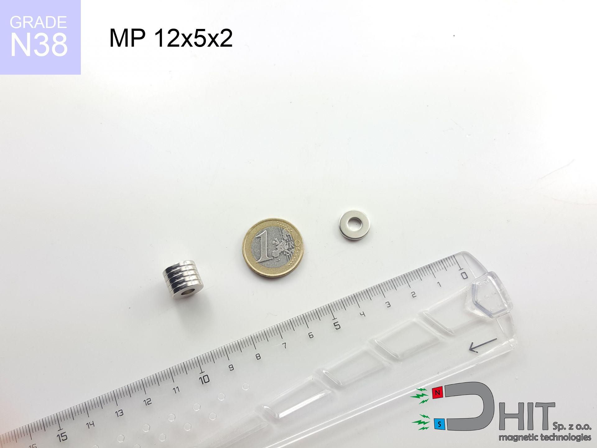
MP 12x5x2 / N38 - ring magnet
ring magnet
Catalog no 030498
Diameter
12 mm [±0,1 mm]
internal diameter Ø
5 mm [±0,1 mm]
Height
2 mm [±0,1 mm]
Weight
1.4 g
Magnetization Direction
↑ axial
Load capacity
1.15 kg / 11.29 N
Magnetic Induction
195.97 mT / 1960 Gs
Coating
[NiCuNi] Nickel
1.230 ZŁ with VAT / pcs + price for transport
1.000 ZŁ net + 23% VAT / pcs
bulk discounts:
Need more?
Contact us by phone
+48 888 99 98 98
otherwise contact us through
request form
through our site.
Strength and appearance of a neodymium magnet can be checked with our
modular calculator.
Orders placed before 14:00 will be shipped the same business day.
Technical - MP 12x5x2 / N38 - ring magnet
Specification / characteristics - MP 12x5x2 / N38 - ring magnet
| properties | values |
|---|---|
| Cat. no. | 030498 |
| Production/Distribution | Dhit sp. z o.o. |
| Country of origin | Poland / China / Germany |
| Customs code | 85059029 |
| Diameter | 12 mm [±0,1 mm] |
| internal diameter Ø | 5 mm [±0,1 mm] |
| Height | 2 mm [±0,1 mm] |
| Weight | 1.4 g |
| Magnetization Direction | ↑ axial |
| Load capacity ~ ? | 1.15 kg / 11.29 N |
| Magnetic Induction ~ ? | 195.97 mT / 1960 Gs |
| Coating | [NiCuNi] Nickel |
| Manufacturing Tolerance | ±0.1 mm |
Magnetic properties of material N38
| properties | values | units |
|---|---|---|
| remenance Br [min. - max.] ? | 12.2-12.6 | kGs |
| remenance Br [min. - max.] ? | 1220-1260 | mT |
| coercivity bHc ? | 10.8-11.5 | kOe |
| coercivity bHc ? | 860-915 | kA/m |
| actual internal force iHc | ≥ 12 | kOe |
| actual internal force iHc | ≥ 955 | kA/m |
| energy density [min. - max.] ? | 36-38 | BH max MGOe |
| energy density [min. - max.] ? | 287-303 | BH max KJ/m |
| max. temperature ? | ≤ 80 | °C |
Physical properties of sintered neodymium magnets Nd2Fe14B at 20°C
| properties | values | units |
|---|---|---|
| Vickers hardness | ≥550 | Hv |
| Density | ≥7.4 | g/cm3 |
| Curie Temperature TC | 312 - 380 | °C |
| Curie Temperature TF | 593 - 716 | °F |
| Specific resistance | 150 | μΩ⋅cm |
| Bending strength | 250 | MPa |
| Compressive strength | 1000~1100 | MPa |
| Thermal expansion parallel (∥) to orientation (M) | (3-4) x 10-6 | °C-1 |
| Thermal expansion perpendicular (⊥) to orientation (M) | -(1-3) x 10-6 | °C-1 |
| Young's modulus | 1.7 x 10⁴ | kg/mm² |
Physical simulation of the assembly - technical parameters
Presented values represent the result of a physical analysis. Values are based on models for the material Nd2Fe14B. Operational conditions might slightly differ. Please consider these data as a supplementary guide during assembly planning.
Table 1: Static force (pull vs gap) - interaction chart
MP 12x5x2 / N38
| Distance (mm) | Induction (Gauss) / mT | Pull Force (kg/lbs/g/N) | Risk Status |
|---|---|---|---|
| 0 mm |
6085 Gs
608.5 mT
|
1.15 kg / 2.54 LBS
1150.0 g / 11.3 N
|
weak grip |
| 1 mm |
5082 Gs
508.2 mT
|
0.80 kg / 1.77 LBS
802.2 g / 7.9 N
|
weak grip |
| 2 mm |
4147 Gs
414.7 mT
|
0.53 kg / 1.18 LBS
534.0 g / 5.2 N
|
weak grip |
| 3 mm |
3340 Gs
334.0 mT
|
0.35 kg / 0.76 LBS
346.3 g / 3.4 N
|
weak grip |
| 5 mm |
2152 Gs
215.2 mT
|
0.14 kg / 0.32 LBS
143.8 g / 1.4 N
|
weak grip |
| 10 mm |
822 Gs
82.2 mT
|
0.02 kg / 0.05 LBS
21.0 g / 0.2 N
|
weak grip |
| 15 mm |
394 Gs
39.4 mT
|
0.00 kg / 0.01 LBS
4.8 g / 0.0 N
|
weak grip |
| 20 mm |
221 Gs
22.1 mT
|
0.00 kg / 0.00 LBS
1.5 g / 0.0 N
|
weak grip |
| 30 mm |
92 Gs
9.2 mT
|
0.00 kg / 0.00 LBS
0.3 g / 0.0 N
|
weak grip |
| 50 mm |
28 Gs
2.8 mT
|
0.00 kg / 0.00 LBS
0.0 g / 0.0 N
|
weak grip |
Table 2: Shear hold (vertical surface)
MP 12x5x2 / N38
| Distance (mm) | Friction coefficient | Pull Force (kg/lbs/g/N) |
|---|---|---|
| 0 mm | Stal (~0.2) |
0.23 kg / 0.51 LBS
230.0 g / 2.3 N
|
| 1 mm | Stal (~0.2) |
0.16 kg / 0.35 LBS
160.0 g / 1.6 N
|
| 2 mm | Stal (~0.2) |
0.11 kg / 0.23 LBS
106.0 g / 1.0 N
|
| 3 mm | Stal (~0.2) |
0.07 kg / 0.15 LBS
70.0 g / 0.7 N
|
| 5 mm | Stal (~0.2) |
0.03 kg / 0.06 LBS
28.0 g / 0.3 N
|
| 10 mm | Stal (~0.2) |
0.00 kg / 0.01 LBS
4.0 g / 0.0 N
|
| 15 mm | Stal (~0.2) |
0.00 kg / 0.00 LBS
0.0 g / 0.0 N
|
| 20 mm | Stal (~0.2) |
0.00 kg / 0.00 LBS
0.0 g / 0.0 N
|
| 30 mm | Stal (~0.2) |
0.00 kg / 0.00 LBS
0.0 g / 0.0 N
|
| 50 mm | Stal (~0.2) |
0.00 kg / 0.00 LBS
0.0 g / 0.0 N
|
Table 3: Wall mounting (sliding) - behavior on slippery surfaces
MP 12x5x2 / N38
| Surface type | Friction coefficient / % Mocy | Max load (kg/lbs/g/N) |
|---|---|---|
| Raw steel |
µ = 0.3
30% Nominalnej Siły
|
0.35 kg / 0.76 LBS
345.0 g / 3.4 N
|
| Painted steel (standard) |
µ = 0.2
20% Nominalnej Siły
|
0.23 kg / 0.51 LBS
230.0 g / 2.3 N
|
| Oily/slippery steel |
µ = 0.1
10% Nominalnej Siły
|
0.11 kg / 0.25 LBS
115.0 g / 1.1 N
|
| Magnet with anti-slip rubber |
µ = 0.5
50% Nominalnej Siły
|
0.58 kg / 1.27 LBS
575.0 g / 5.6 N
|
Table 4: Steel thickness (substrate influence) - sheet metal selection
MP 12x5x2 / N38
| Steel thickness (mm) | % power | Real pull force (kg/lbs/g/N) |
|---|---|---|
| 0.5 mm |
|
0.11 kg / 0.25 LBS
115.0 g / 1.1 N
|
| 1 mm |
|
0.29 kg / 0.63 LBS
287.5 g / 2.8 N
|
| 2 mm |
|
0.58 kg / 1.27 LBS
575.0 g / 5.6 N
|
| 3 mm |
|
0.86 kg / 1.90 LBS
862.5 g / 8.5 N
|
| 5 mm |
|
1.15 kg / 2.54 LBS
1150.0 g / 11.3 N
|
| 10 mm |
|
1.15 kg / 2.54 LBS
1150.0 g / 11.3 N
|
| 11 mm |
|
1.15 kg / 2.54 LBS
1150.0 g / 11.3 N
|
| 12 mm |
|
1.15 kg / 2.54 LBS
1150.0 g / 11.3 N
|
Table 5: Thermal stability (stability) - power drop
MP 12x5x2 / N38
| Ambient temp. (°C) | Power loss | Remaining pull (kg/lbs/g/N) | Status |
|---|---|---|---|
| 20 °C | 0.0% |
1.15 kg / 2.54 LBS
1150.0 g / 11.3 N
|
OK |
| 40 °C | -2.2% |
1.12 kg / 2.48 LBS
1124.7 g / 11.0 N
|
OK |
| 60 °C | -4.4% |
1.10 kg / 2.42 LBS
1099.4 g / 10.8 N
|
OK |
| 80 °C | -6.6% |
1.07 kg / 2.37 LBS
1074.1 g / 10.5 N
|
|
| 100 °C | -28.8% |
0.82 kg / 1.81 LBS
818.8 g / 8.0 N
|
Table 6: Magnet-Magnet interaction (attraction) - forces in the system
MP 12x5x2 / N38
| Gap (mm) | Attraction (kg/lbs) (N-S) | Sliding Force (kg/lbs/g/N) | Repulsion (kg/lbs) (N-N) |
|---|---|---|---|
| 0 mm |
21.34 kg / 47.04 LBS
6 163 Gs
|
3.20 kg / 7.06 LBS
3201 g / 31.4 N
|
N/A |
| 1 mm |
17.97 kg / 39.61 LBS
11 168 Gs
|
2.69 kg / 5.94 LBS
2695 g / 26.4 N
|
16.17 kg / 35.65 LBS
~0 Gs
|
| 2 mm |
14.88 kg / 32.81 LBS
10 165 Gs
|
2.23 kg / 4.92 LBS
2233 g / 21.9 N
|
13.40 kg / 29.53 LBS
~0 Gs
|
| 3 mm |
12.20 kg / 26.89 LBS
9 202 Gs
|
1.83 kg / 4.03 LBS
1830 g / 17.9 N
|
10.98 kg / 24.20 LBS
~0 Gs
|
| 5 mm |
8.00 kg / 17.63 LBS
7 450 Gs
|
1.20 kg / 2.64 LBS
1199 g / 11.8 N
|
7.20 kg / 15.87 LBS
~0 Gs
|
| 10 mm |
2.67 kg / 5.88 LBS
4 304 Gs
|
0.40 kg / 0.88 LBS
400 g / 3.9 N
|
2.40 kg / 5.30 LBS
~0 Gs
|
| 20 mm |
0.39 kg / 0.86 LBS
1 644 Gs
|
0.06 kg / 0.13 LBS
58 g / 0.6 N
|
0.35 kg / 0.77 LBS
~0 Gs
|
| 50 mm |
0.01 kg / 0.02 LBS
275 Gs
|
0.00 kg / 0.00 LBS
2 g / 0.0 N
|
0.01 kg / 0.02 LBS
~0 Gs
|
| 60 mm |
0.00 kg / 0.01 LBS
184 Gs
|
0.00 kg / 0.00 LBS
1 g / 0.0 N
|
0.00 kg / 0.00 LBS
~0 Gs
|
| 70 mm |
0.00 kg / 0.01 LBS
129 Gs
|
0.00 kg / 0.00 LBS
0 g / 0.0 N
|
0.00 kg / 0.00 LBS
~0 Gs
|
| 80 mm |
0.00 kg / 0.00 LBS
95 Gs
|
0.00 kg / 0.00 LBS
0 g / 0.0 N
|
0.00 kg / 0.00 LBS
~0 Gs
|
| 90 mm |
0.00 kg / 0.00 LBS
72 Gs
|
0.00 kg / 0.00 LBS
0 g / 0.0 N
|
0.00 kg / 0.00 LBS
~0 Gs
|
| 100 mm |
0.00 kg / 0.00 LBS
56 Gs
|
0.00 kg / 0.00 LBS
0 g / 0.0 N
|
0.00 kg / 0.00 LBS
~0 Gs
|
Table 7: Protective zones (electronics) - warnings
MP 12x5x2 / N38
| Object / Device | Limit (Gauss) / mT | Safe distance |
|---|---|---|
| Pacemaker | 5 Gs (0.5 mT) | 10.0 cm |
| Hearing aid | 10 Gs (1.0 mT) | 8.0 cm |
| Mechanical watch | 20 Gs (2.0 mT) | 6.0 cm |
| Mobile device | 40 Gs (4.0 mT) | 4.5 cm |
| Remote | 50 Gs (5.0 mT) | 4.0 cm |
| Payment card | 400 Gs (40.0 mT) | 1.5 cm |
| HDD hard drive | 600 Gs (60.0 mT) | 1.5 cm |
Table 8: Impact energy (cracking risk) - collision effects
MP 12x5x2 / N38
| Start from (mm) | Speed (km/h) | Energy (J) | Predicted outcome |
|---|---|---|---|
| 10 mm |
29.23 km/h
(8.12 m/s)
|
0.05 J | |
| 30 mm |
50.07 km/h
(13.91 m/s)
|
0.14 J | |
| 50 mm |
64.63 km/h
(17.95 m/s)
|
0.23 J | |
| 100 mm |
91.40 km/h
(25.39 m/s)
|
0.45 J |
Table 9: Surface protection spec
MP 12x5x2 / N38
| Technical parameter | Value / Description |
|---|---|
| Coating type | [NiCuNi] Nickel |
| Layer structure | Nickel - Copper - Nickel |
| Layer thickness | 10-20 µm |
| Salt spray test (SST) ? | 24 h |
| Recommended environment | Indoors only (dry) |
Table 10: Construction data (Flux)
MP 12x5x2 / N38
| Parameter | Value | SI Unit / Description |
|---|---|---|
| Magnetic Flux | 6 503 Mx | 65.0 µWb |
| Pc Coefficient | 1.34 | High (Stable) |
Table 11: Physics of underwater searching
MP 12x5x2 / N38
| Environment | Effective steel pull | Effect |
|---|---|---|
| Air (land) | 1.15 kg | Standard |
| Water (riverbed) |
1.32 kg
(+0.17 kg buoyancy gain)
|
+14.5% |
1. Vertical hold
*Note: On a vertical surface, the magnet holds merely approx. 20-30% of its nominal pull.
2. Plate thickness effect
*Thin steel (e.g. computer case) drastically reduces the holding force.
3. Temperature resistance
*For N38 material, the max working temp is 80°C.
4. Demagnetization curve and operating point (B-H)
chart generated for the permeance coefficient Pc (Permeance Coefficient) = 1.34
The chart above illustrates the magnetic characteristics of the material within the second quadrant of the hysteresis loop. The solid red line represents the demagnetization curve (material potential), while the dashed blue line is the load line based on the magnet's geometry. The Pc (Permeance Coefficient), also known as the load line slope, is a dimensionless value that describes the relationship between the magnet's shape and its magnetic stability. The intersection of these two lines (the black dot) is the operating point — it determines the actual magnetic flux density generated by the magnet in this specific configuration. A higher Pc value means the magnet is more 'slender' (tall relative to its area), resulting in a higher operating point and better resistance to irreversible demagnetization caused by external fields or temperature. A value of 0.42 is relatively low (typical for flat magnets), meaning the operating point is closer to the 'knee' of the curve — caution is advised when operating at temperatures near the maximum limit to avoid strength loss.
Material specification
| iron (Fe) | 64% – 68% |
| neodymium (Nd) | 29% – 32% |
| boron (B) | 1.1% – 1.2% |
| dysprosium (Dy) | 0.5% – 2.0% |
| coating (Ni-Cu-Ni) | < 0.05% |
Ecology and recycling (GPSR)
| recyclability (EoL) | 100% |
| recycled raw materials | ~10% (pre-cons) |
| carbon footprint | low / zredukowany |
| waste code (EWC) | 16 02 16 |
Other proposals
![BM 510x180x70 [4x M8] - magnetic beam](https://cdn3.dhit.pl/graphics/products/bm-510x180x70-4x-m8-cem.jpg "BM 510x180x70 [4x M8] - magnetic beam")
![UMGZ 36x18x8 [M6] GZ / N38 - magnetic holder external thread](https://cdn3.dhit.pl/graphics/products/um-36x18x8-m8-gz-xiv.jpg "UMGZ 36x18x8 [M6] GZ / N38 - magnetic holder external thread")
![UMH 42x9x46 [M6] / N38 - magnetic holder with hook](https://cdn3.dhit.pl/graphics/products/umh-42x9x46-m6-vat.jpg "UMH 42x9x46 [M6] / N38 - magnetic holder with hook")

Pros and cons of neodymium magnets.
Advantages
- They virtually do not lose power, because even after ten years the decline in efficiency is only ~1% (based on calculations),
- They maintain their magnetic properties even under external field action,
- In other words, due to the glossy finish of silver, the element gains visual value,
- They are known for high magnetic induction at the operating surface, which improves attraction properties,
- Due to their durability and thermal resistance, neodymium magnets are capable of operate (depending on the form) even at high temperatures reaching 230°C or more...
- Considering the potential of free forming and customization to specialized solutions, neodymium magnets can be modeled in a broad palette of shapes and sizes, which amplifies use scope,
- Significant place in electronics industry – they are used in magnetic memories, electric drive systems, precision medical tools, as well as complex engineering applications.
- Thanks to efficiency per cm³, small magnets offer high operating force, in miniature format,
Limitations
- Susceptibility to cracking is one of their disadvantages. Upon intense impact they can break. We advise keeping them in a special holder, which not only secures them against impacts but also increases their durability
- Neodymium magnets lose their power under the influence of heating. As soon as 80°C is exceeded, many of them start losing their power. Therefore, we recommend our special magnets marked [AH], which maintain stability even at temperatures up to 230°C
- They rust in a humid environment - during use outdoors we advise using waterproof magnets e.g. in rubber, plastic
- Due to limitations in creating threads and complex forms in magnets, we propose using cover - magnetic mechanism.
- Potential hazard to health – tiny shards of magnets are risky, when accidentally swallowed, which gains importance in the context of child health protection. Furthermore, tiny parts of these products can complicate diagnosis medical in case of swallowing.
- Higher cost of purchase is a significant factor to consider compared to ceramic magnets, especially in budget applications
Pull force analysis
Maximum holding power of the magnet – what contributes to it?
- with the contact of a sheet made of special test steel, ensuring full magnetic saturation
- with a cross-section no less than 10 mm
- with a surface perfectly flat
- under conditions of gap-free contact (surface-to-surface)
- under axial application of breakaway force (90-degree angle)
- at ambient temperature room level
Practical aspects of lifting capacity – factors
- Gap between magnet and steel – every millimeter of distance (caused e.g. by varnish or dirt) diminishes the pulling force, often by half at just 0.5 mm.
- Loading method – declared lifting capacity refers to detachment vertically. When applying parallel force, the magnet exhibits much less (typically approx. 20-30% of maximum force).
- Plate thickness – insufficiently thick steel does not close the flux, causing part of the power to be lost into the air.
- Steel type – mild steel gives the best results. Higher carbon content lower magnetic permeability and holding force.
- Surface structure – the more even the surface, the larger the contact zone and stronger the hold. Roughness acts like micro-gaps.
- Thermal conditions – neodymium magnets have a negative temperature coefficient. When it is hot they lose power, and in frost they can be stronger (up to a certain limit).
Holding force was tested on the plate surface of 20 mm thickness, when the force acted perpendicularly, in contrast under parallel forces the load capacity is reduced by as much as fivefold. In addition, even a minimal clearance between the magnet and the plate lowers the holding force.
Warnings
Swallowing risk
Always keep magnets away from children. Risk of swallowing is high, and the consequences of magnets clamping inside the body are fatal.
Threat to navigation
A powerful magnetic field disrupts the functioning of magnetometers in smartphones and GPS navigation. Do not bring magnets near a device to avoid breaking the sensors.
Demagnetization risk
Keep cool. Neodymium magnets are sensitive to temperature. If you require resistance above 80°C, ask us about special high-temperature series (H, SH, UH).
Handling guide
Exercise caution. Neodymium magnets attract from a distance and connect with huge force, often faster than you can react.
Life threat
For implant holders: Powerful magnets affect electronics. Maintain minimum 30 cm distance or request help to handle the magnets.
Material brittleness
Beware of splinters. Magnets can fracture upon uncontrolled impact, ejecting shards into the air. Wear goggles.
Allergic reactions
It is widely known that the nickel plating (standard magnet coating) is a strong allergen. If your skin reacts to metals, refrain from touching magnets with bare hands or select coated magnets.
Electronic hazard
Do not bring magnets near a purse, computer, or screen. The magnetism can permanently damage these devices and erase data from cards.
Physical harm
Big blocks can break fingers instantly. Under no circumstances put your hand between two attracting surfaces.
Dust is flammable
Dust created during grinding of magnets is flammable. Avoid drilling into magnets unless you are an expert.
Tabela kosztu i czasu dostawy
Płatność przed wysyłką:

GLS kurier
Przesyłka będzie u Ciebie za 2-3 dni
14.99 ZŁ

InPost Paczkomaty 24/7
Przesyłka będzie u Ciebie za 1-2 dni
12.30 ZŁ
Płatność przy odbiorze (pobranie):
GLS kurier
Przesyłka będzie u Ciebie za 1-2 dni
23.00 ZŁ
Rate the product
Your rating