

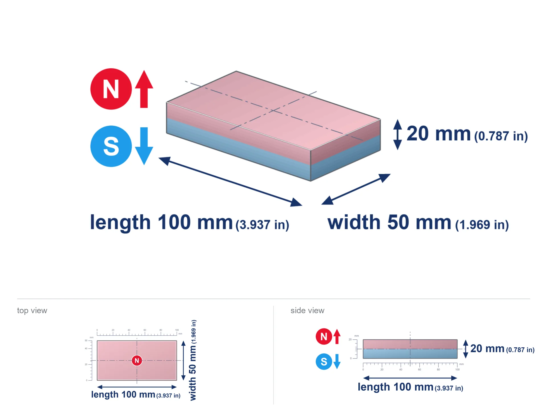
MPL 100x50x20 / N38 - lamellar magnet
lamellar magnet
Catalog no 020581
GTIN/EAN: 5906301815747
- length
- 100 mm [±0,1 mm]
- Width
- 50 mm [±0,1 mm]
- Height
- 20 mm [±0,1 mm]
- Weight
- 750 g
- Magnetization Direction
- ↑ axial
- Coating
- [NiCuNi] Nickel
How we measure these parameters — certificates and measurements
232.97 zł net / pcs
286.55 zł with VAT (23% VAT) / pcs
bulk discounts:
Need more?Frequently asked questions
What pull rating should I choose for a workshop block magnet?
Are block neodymium magnets available in more durable versions?
How should I choose block magnets for mounting a structure?
Engineering report for this magnet
Full PDF analysis: pull and shear force, effect of distance, temperature and plate thickness, safety distances and the demagnetization curve.
Call us now
+48 888 99 98 98
alternatively let us know using
contact form
the contact section.
Specifications and structure of a neodymium magnet can be estimated using our
power calculator.
Order by 14:00 and we’ll ship today!
Physical properties - MPL 100x50x20 / N38 - lamellar magnet
Specification / characteristics - MPL 100x50x20 / N38 - lamellar magnet
| properties | values |
|---|---|
| Cat. no. | 020581 |
| GTIN/EAN | 5906301815747 |
| Distributor | Dhit sp. z o.o. |
| Country of origin | Poland / China / Germany |
| Customs code | 85059029 |
| length | 100 mm [±0,1 mm] |
| Width | 50 mm [±0,1 mm] |
| Height | 20 mm [±0,1 mm] |
| Weight | 750 g |
| Magnetization Direction | ↑ axial |
| Load capacity ~ ? | 123.52 kg / 1211.32 N |
| Magnetic Induction ~ ? | 299.83 mT / 2998 Gs |
| Coating | [NiCuNi] Nickel |
| Manufacturing Tolerance | ±0.1 mm |
Magnetic properties of material N38
| properties | values | units |
|---|---|---|
| Remanence Br ? | 12.2-12.6 | kGs |
| Remanence Br ? | 1220-1260 | mT |
| Coercivity bHc ? | 10.8-11.5 | kOe |
| Coercivity bHc ? | 860-915 | kA/m |
| Intrinsic coercivity iHc | ≥ 12 | kOe |
| Intrinsic coercivity iHc | ≥ 955 | kA/m |
| Energy product BHmax ? | 36-38 | BH max MGOe |
| Energy product BHmax ? | 287-303 | BH max KJ/m |
| Maximum working temperature ? | ≤ 80 | °C |
Physical properties of sintered neodymium magnets Nd2Fe14B at 20°C
| properties | values | units |
|---|---|---|
| Vickers hardness | ≥550 | Hv |
| Density | ≥7.4 | g/cm3 |
| Curie Temperature TC | 310 | °C |
| Curie Temperature TF | 590 | °F |
| Specific resistance | 150 | μΩ⋅cm |
| Bending strength | 250 | MPa |
| Compressive strength | 1000~1100 | MPa |
| Thermal expansion parallel (∥) to orientation (M) | (3-4) x 10-6 | °C-1 |
| Thermal expansion perpendicular (⊥) to orientation (M) | -(1-3) x 10-6 | °C-1 |
| Young's modulus | 1.7 x 10⁴ | kg/mm² |
Engineering analysis of the product - report
Presented values constitute the direct effect of a mathematical simulation. Results were calculated on models for the material Nd2Fe14B. Actual conditions may deviate from the simulation results. Please consider these data as a supplementary guide when designing systems.
Table 1: Static force (force vs distance) - characteristics
MPL 100x50x20 / N38
| Distance (mm) | Induction (Gauss) / mT | Pull Force (kg/lbs/g/N) | Risk Status |
|---|---|---|---|
| 0 mm |
2998 Gs
299.8 mT
|
123.52 kg / 272.31 pounds
123520.0 g / 1211.7 N
|
dangerous! |
| 1 mm |
2930 Gs
293.0 mT
|
117.97 kg / 260.08 pounds
117971.9 g / 1157.3 N
|
dangerous! |
| 2 mm |
2858 Gs
285.8 mT
|
112.22 kg / 247.40 pounds
112220.3 g / 1100.9 N
|
dangerous! |
| 3 mm |
2782 Gs
278.2 mT
|
106.39 kg / 234.55 pounds
106390.3 g / 1043.7 N
|
dangerous! |
| 5 mm |
2626 Gs
262.6 mT
|
94.75 kg / 208.88 pounds
94746.3 g / 929.5 N
|
dangerous! |
| 10 mm |
2223 Gs
222.3 mT
|
67.92 kg / 149.74 pounds
67921.7 g / 666.3 N
|
dangerous! |
| 15 mm |
1845 Gs
184.5 mT
|
46.78 kg / 103.13 pounds
46780.7 g / 458.9 N
|
dangerous! |
| 20 mm |
1517 Gs
151.7 mT
|
31.63 kg / 69.73 pounds
31630.7 g / 310.3 N
|
dangerous! |
| 30 mm |
1024 Gs
102.4 mT
|
14.40 kg / 31.75 pounds
14401.8 g / 141.3 N
|
dangerous! |
| 50 mm |
493 Gs
49.3 mT
|
3.34 kg / 7.37 pounds
3344.8 g / 32.8 N
|
warning |
Table 2: Sliding load (wall)
MPL 100x50x20 / N38
| Distance (mm) | Friction coefficient | Pull Force (kg/lbs/g/N) |
|---|---|---|
| 0 mm | Raw steel (µ ≈ 0.2) |
24.70 kg / 54.46 pounds
24704.0 g / 242.3 N
|
| 1 mm | Raw steel (µ ≈ 0.2) |
23.59 kg / 52.02 pounds
23594.0 g / 231.5 N
|
| 2 mm | Raw steel (µ ≈ 0.2) |
22.44 kg / 49.48 pounds
22444.0 g / 220.2 N
|
| 3 mm | Raw steel (µ ≈ 0.2) |
21.28 kg / 46.91 pounds
21278.0 g / 208.7 N
|
| 5 mm | Raw steel (µ ≈ 0.2) |
18.95 kg / 41.78 pounds
18950.0 g / 185.9 N
|
| 10 mm | Raw steel (µ ≈ 0.2) |
13.58 kg / 29.95 pounds
13584.0 g / 133.3 N
|
| 15 mm | Raw steel (µ ≈ 0.2) |
9.36 kg / 20.63 pounds
9356.0 g / 91.8 N
|
| 20 mm | Raw steel (µ ≈ 0.2) |
6.33 kg / 13.95 pounds
6326.0 g / 62.1 N
|
| 30 mm | Raw steel (µ ≈ 0.2) |
2.88 kg / 6.35 pounds
2880.0 g / 28.3 N
|
| 50 mm | Raw steel (µ ≈ 0.2) |
0.67 kg / 1.47 pounds
668.0 g / 6.6 N
|
Table 3: Vertical assembly (shearing) - behavior on slippery surfaces
MPL 100x50x20 / N38
| Surface type | Friction coefficient / % | Max load (kg/lbs/g/N) |
|---|---|---|
| Raw steel |
µ = 0.3
30% of nominal force
|
37.06 kg / 81.69 pounds
37056.0 g / 363.5 N
|
| Painted steel (standard) |
µ = 0.2
20% of nominal force
|
24.70 kg / 54.46 pounds
24704.0 g / 242.3 N
|
| Oily/slippery steel |
µ = 0.1
10% of nominal force
|
12.35 kg / 27.23 pounds
12352.0 g / 121.2 N
|
| Magnet with anti-slip rubber |
µ = 0.5
50% of nominal force
|
61.76 kg / 136.16 pounds
61760.0 g / 605.9 N
|
Table 4: Steel thickness (substrate influence) - sheet metal selection
MPL 100x50x20 / N38
| Steel thickness (mm) | % power | Real pull force (kg/lbs/g/N) |
|---|---|---|
| 0.5 mm |
|
4.12 kg / 9.08 pounds
4117.3 g / 40.4 N
|
| 1 mm |
|
10.29 kg / 22.69 pounds
10293.3 g / 101.0 N
|
| 2 mm |
|
20.59 kg / 45.39 pounds
20586.7 g / 202.0 N
|
| 3 mm |
|
30.88 kg / 68.08 pounds
30880.0 g / 302.9 N
|
| 5 mm |
|
51.47 kg / 113.46 pounds
51466.7 g / 504.9 N
|
| 10 mm |
|
102.93 kg / 226.93 pounds
102933.3 g / 1009.8 N
|
| 11 mm |
|
113.23 kg / 249.62 pounds
113226.7 g / 1110.8 N
|
| 12 mm |
|
123.52 kg / 272.31 pounds
123520.0 g / 1211.7 N
|
Table 5: Thermal resistance (stability) - resistance threshold
MPL 100x50x20 / N38
| Magnet temperature (°C) | Force change relative to 20°C | Remaining pull (kg/lbs/g/N) | Status |
|---|---|---|---|
| 20 °C | 0.0% |
123.52 kg / 272.31 pounds
123520.0 g / 1211.7 N
|
Estimate |
| 40 °C | -4.4% |
118.14 kg / 260.46 pounds
118144.9 g / 1159.0 N
|
Estimate |
| 60 °C | -8.6% |
112.89 kg / 248.88 pounds
112889.4 g / 1107.4 N
|
Estimate |
| 80 °C | -12.8% |
107.75 kg / 237.56 pounds
107753.4 g / 1057.1 N
|
Material limit |
| 100 °C | — | — | Out of range — no model |
Table 6: Two magnets (attraction) - field collision
MPL 100x50x20 / N38
| Gap (mm) | Attraction (kg/lbs) (N-S) | Shear Strength (kg/lbs/g/N) | Repulsion (kg/lbs) (N-N) |
|---|---|---|---|
| 0 mm |
277.06 kg / 610.82 pounds
4 515 Gs
|
41.56 kg / 91.62 pounds
41560 g / 407.7 N
|
N/A |
| 1 mm |
270.95 kg / 597.35 pounds
5 930 Gs
|
40.64 kg / 89.60 pounds
40643 g / 398.7 N
|
243.86 kg / 537.62 pounds
~0 Gs
|
| 2 mm |
264.62 kg / 583.38 pounds
5 860 Gs
|
39.69 kg / 87.51 pounds
39693 g / 389.4 N
|
238.16 kg / 525.05 pounds
~0 Gs
|
| 3 mm |
258.20 kg / 569.23 pounds
5 788 Gs
|
38.73 kg / 85.38 pounds
38730 g / 379.9 N
|
232.38 kg / 512.31 pounds
~0 Gs
|
| 5 mm |
245.19 kg / 540.55 pounds
5 641 Gs
|
36.78 kg / 81.08 pounds
36779 g / 360.8 N
|
220.67 kg / 486.50 pounds
~0 Gs
|
| 10 mm |
212.52 kg / 468.53 pounds
5 251 Gs
|
31.88 kg / 70.28 pounds
31878 g / 312.7 N
|
191.27 kg / 421.68 pounds
~0 Gs
|
| 20 mm |
152.35 kg / 335.88 pounds
4 446 Gs
|
22.85 kg / 50.38 pounds
22853 g / 224.2 N
|
137.12 kg / 302.29 pounds
~0 Gs
|
| 50 mm |
47.77 kg / 105.32 pounds
2 490 Gs
|
7.17 kg / 15.80 pounds
7166 g / 70.3 N
|
43.00 kg / 94.79 pounds
~0 Gs
|
| 60 mm |
32.30 kg / 71.22 pounds
2 047 Gs
|
4.85 kg / 10.68 pounds
4846 g / 47.5 N
|
29.07 kg / 64.10 pounds
~0 Gs
|
| 70 mm |
22.04 kg / 48.58 pounds
1 691 Gs
|
3.31 kg / 7.29 pounds
3305 g / 32.4 N
|
19.83 kg / 43.72 pounds
~0 Gs
|
| 80 mm |
15.20 kg / 33.51 pounds
1 404 Gs
|
2.28 kg / 5.03 pounds
2280 g / 22.4 N
|
13.68 kg / 30.16 pounds
~0 Gs
|
| 90 mm |
10.61 kg / 23.40 pounds
1 173 Gs
|
1.59 kg / 3.51 pounds
1592 g / 15.6 N
|
9.55 kg / 21.06 pounds
~0 Gs
|
| 100 mm |
7.50 kg / 16.54 pounds
987 Gs
|
1.13 kg / 2.48 pounds
1125 g / 11.0 N
|
6.75 kg / 14.89 pounds
~0 Gs
|
Table 7: Axial field levels — not safety zones
MPL 100x50x20 / N38
| Field level (Gs) | mT | Model distance (cm) |
|---|---|---|
| < 5 Gs | < 0.5 mT | 33.0 cm |
| < 10 Gs | < 1.0 mT | 26.0 cm |
| < 20 Gs | < 2.0 mT | 20.0 cm |
| < 40 Gs | < 4.0 mT | 15.5 cm |
| < 50 Gs | < 5.0 mT | 14.5 cm |
| < 400 Gs | < 40.0 mT | 6.0 cm |
| < 600 Gs | < 60.0 mT | 4.5 cm |
Table 8: Impact energy (cracking risk) - collision effects
MPL 100x50x20 / N38
| Start from (mm) | Speed (km/h) | Energy (J) | Predicted outcome |
|---|---|---|---|
| 10 mm |
17.96 km/h
(4.99 m/s)
|
9.33 J | |
| 30 mm |
23.64 km/h
(6.57 m/s)
|
16.17 J | |
| 50 mm |
24.68 km/h
(6.86 m/s)
|
17.63 J | |
| 100 mm |
25.03 km/h
(6.95 m/s)
|
18.13 J |
Table 9: Corrosion resistance
MPL 100x50x20 / N38
| Technical parameter | Value / Description |
|---|---|
| Coating type | [NiCuNi] Nickel |
| Layer structure | Nickel - Copper - Nickel |
| Layer thickness | 10-20 µm |
| Salt spray test (SST) ? | 24 h |
| Recommended environment | Indoors only (dry) |
Table 10: Electrical data (Flux)
MPL 100x50x20 / N38
| Parameter | Value | SI Unit / Description |
|---|---|---|
| Magnetic Flux | 154 231 Mx | 1542.3 µWb |
| Pc Coefficient | 0.35 | Low (Flat) |
Table 11: Hydrostatics and buoyancy
MPL 100x50x20 / N38
| Environment | Effective steel pull | Effect |
|---|---|---|
| Air (land) | 123.52 kg | Standard |
| Water (riverbed) |
141.43 kg
(+17.91 kg buoyancy gain)
|
+14.5% |
1. Sliding resistance
*Caution: On a vertical wall, the magnet holds merely a fraction of its perpendicular strength.
2. Steel saturation
*Thin metal sheet (e.g. computer case) significantly limits the holding force.
3. Thermal stability
N38: the maximum material working temperature is 80°C. Permitted conditions also depend on the shape and magnetic circuit.
4. Demagnetization curve and operating point (B-H)
chart generated for the permeance coefficient Pc (Permeance Coefficient) = 0.35
This simulation demonstrates the magnetic stability of the selected magnet under specific geometric conditions. The solid red line represents the demagnetization curve (material potential), while the dashed blue line is the load line based on the magnet's geometry. The Pc (Permeance Coefficient), also known as the load line slope, is a dimensionless value that describes the relationship between the magnet's shape and its magnetic stability. The intersection of these two lines (the black dot) is the operating point — it determines the actual magnetic flux density generated by the magnet in this specific configuration. A higher Pc value means the magnet is more 'slender' (tall relative to its area), resulting in a higher operating point and better resistance to irreversible demagnetization caused by external fields or temperature. A value of 0.42 is relatively low (typical for flat magnets), meaning the operating point is closer to the 'knee' of the curve — caution is advised when operating at temperatures near the maximum limit to avoid strength loss.
Chemical composition
| iron (Fe) | 64% – 68% |
| neodymium (Nd) | 29% – 32% |
| boron (B) | 1.1% – 1.2% |
| dysprosium (Dy) | 0.5% – 2.0% |
| coating (Ni-Cu-Ni) | < 0.05% |
Sustainability
| recyclability (EoL) | 100% |
| recycled raw materials | ~10% (pre-cons) |
| carbon footprint | low / zredukowany |
| waste code (EWC) | 16 02 16 |
View more proposals
Strengths as well as weaknesses of rare earth magnets.
Strengths
- They do not lose power, even after around ten years – the decrease in power is only ~1% (based on measurements),
- They feature excellent resistance to magnetism drop due to opposing magnetic fields,
- In other words, due to the glossy layer of silver, the element becomes visually attractive,
- Magnets are characterized by maximum magnetic induction on the outer side,
- Thanks to resistance to high temperature, they are able to function (depending on the form) even at temperatures up to 230°C and higher...
- In view of the ability of flexible shaping and customization to custom projects, NdFeB magnets can be modeled in a broad palette of shapes and sizes, which makes them more universal,
- Key role in future technologies – they serve a role in mass storage devices, drive modules, medical devices, also modern systems.
- Relatively small size with high pulling force – neodymium magnets offer high power in tiny dimensions, which enables their usage in compact constructions
Disadvantages
- At very strong impacts they can break, therefore we advise placing them in strong housings. A metal housing provides additional protection against damage, as well as increases the magnet's durability.
- Do not exceed this material temperature limit: 80°C. Overheating may permanently weaken the magnet.
- Magnets exposed to a humid environment can corrode. Therefore when using outdoors, we advise using water-impermeable magnets made of rubber, plastic or other material resistant to moisture
- Limited possibility of creating nuts in the magnet and complex forms - preferred is a housing - mounting mechanism.
- Potential hazard related to microscopic parts of magnets pose a threat, when accidentally swallowed, which gains importance in the aspect of protecting the youngest. It is also worth noting that small elements of these products can be problematic in diagnostics medical when they are in the body.
- Higher cost of purchase is one of the disadvantages compared to ceramic magnets, especially in budget applications
Pull force analysis
Detachment force of the magnet in optimal conditions – what contributes to it?
- using a sheet made of mild steel, acting as a ideal flux conductor
- whose thickness equals approx. 10 mm
- with an polished contact surface
- with direct contact (no paint)
- under perpendicular application of breakaway force (90-degree angle)
- in stable room temperature
Key elements affecting lifting force
- Distance (between the magnet and the plate), because even a tiny clearance (e.g. 0.5 mm) can cause a decrease in lifting capacity by up to 50% (this also applies to varnish, corrosion or dirt).
- Pull-off angle – note that the magnet has greatest strength perpendicularly. Under shear forces, the holding force drops drastically, often to levels of 20-30% of the nominal value.
- Plate thickness – too thin plate causes magnetic saturation, causing part of the flux to be wasted to the other side.
- Metal type – different alloys reacts the same. High carbon content weaken the interaction with the magnet.
- Surface condition – ground elements ensure maximum contact, which increases field saturation. Uneven metal weaken the grip.
- Operating temperature – neodymium magnets have a negative temperature coefficient. When it is hot they lose power, and in frost they can be stronger (up to a certain limit).
Lifting capacity testing was carried out on a smooth plate of suitable thickness, under perpendicular forces, however under parallel forces the load capacity is reduced by as much as 75%. Moreover, even a small distance between the magnet’s surface and the plate decreases the load capacity.
Safety rules for work with NdFeB magnets
This is not a toy
Absolutely store magnets away from children. Risk of swallowing is significant, and the consequences of magnets connecting inside the body are very dangerous.
Beware of splinters
NdFeB magnets are sintered ceramics, which means they are fragile like glass. Clashing of two magnets will cause them breaking into shards.
GPS Danger
A powerful magnetic field interferes with the operation of magnetometers in phones and navigation systems. Maintain magnets close to a device to avoid breaking the sensors.
Health Danger
For implant holders: Strong magnetic fields disrupt medical devices. Keep minimum 30 cm distance or request help to handle the magnets.
Dust explosion hazard
Fire hazard: Neodymium dust is explosive. Avoid machining magnets without safety gear as this may cause fire.
Safe distance
Very strong magnetic fields can erase data on payment cards, hard drives, and other magnetic media. Keep a distance of at least 10 cm.
Nickel coating and allergies
Certain individuals have a hypersensitivity to nickel, which is the typical protective layer for NdFeB magnets. Frequent touching can result in dermatitis. We strongly advise wear protective gloves.
Finger safety
Risk of injury: The pulling power is so great that it can cause blood blisters, crushing, and even bone fractures. Protective gloves are recommended.
Immense force
Use magnets with awareness. Their huge power can shock even experienced users. Plan your moves and respect their force.
Do not overheat magnets
Do not exceed the maximum operating temperature stated in the specifications of the particular product. The limit depends on the material, geometry and operating arrangement; there is no single threshold for all neodymium magnets. Overheating can permanently weaken a magnet.
Tabela kosztu i czasu dostawy
Płatność przed wysyłką:

GLS kurier
Przesyłka będzie u Ciebie za 2-3 dni
14.99 ZŁ

InPost Paczkomaty 24/7
Przesyłka będzie u Ciebie za 1-2 dni
12.30 ZŁ
Płatność przy odbiorze (pobranie):
GLS kurier
Przesyłka będzie u Ciebie za 1-2 dni
23.00 ZŁ