
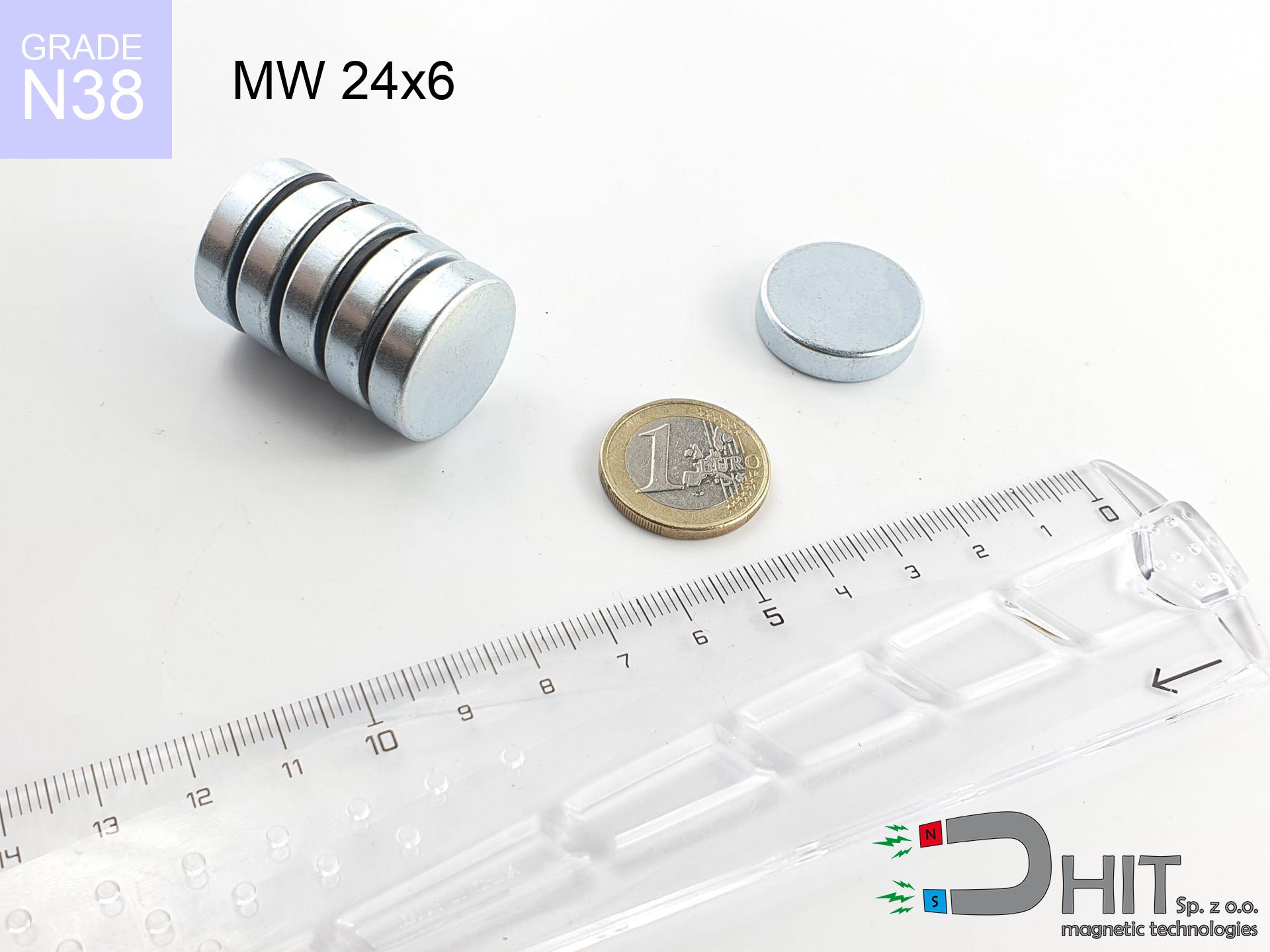
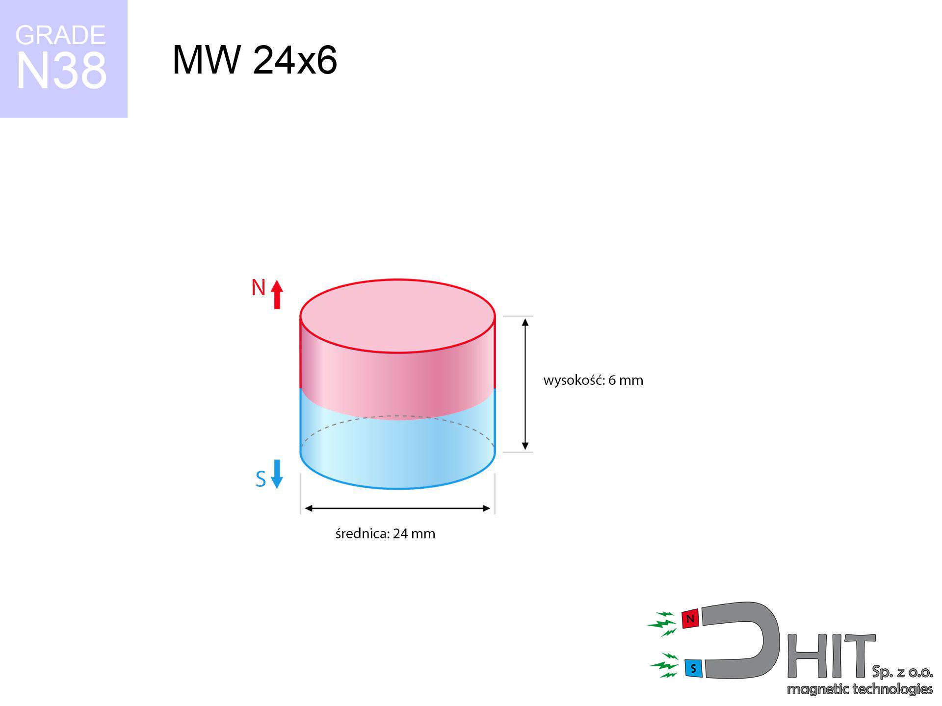
MW 24x6 / N38 - cylindrical magnet
cylindrical magnet
Catalog no 010048
GTIN/EAN: 5906301810476
Diameter Ø
24 mm [±0,1 mm]
Height
6 mm [±0,1 mm]
Weight
20.36 g
Magnetization Direction
↑ axial
Load capacity
9.98 kg / 97.88 N
Magnetic Induction
277.18 mT / 2772 Gs
Coating
[Zn] Zinc
5.10 ZŁ with VAT / pcs + price for transport
4.15 ZŁ net + 23% VAT / pcs
bulk discounts:
Need more?
Give us a call
+48 888 99 98 98
or drop us a message via
inquiry form
the contact section.
Parameters as well as appearance of magnets can be estimated using our
modular calculator.
Orders submitted before 14:00 will be dispatched today!
Detailed specification - MW 24x6 / N38 - cylindrical magnet
Specification / characteristics - MW 24x6 / N38 - cylindrical magnet
| properties | values |
|---|---|
| Cat. no. | 010048 |
| GTIN/EAN | 5906301810476 |
| Production/Distribution | Dhit sp. z o.o. |
| Country of origin | Poland / China / Germany |
| Customs code | 85059029 |
| Diameter Ø | 24 mm [±0,1 mm] |
| Height | 6 mm [±0,1 mm] |
| Weight | 20.36 g |
| Magnetization Direction | ↑ axial |
| Load capacity ~ ? | 9.98 kg / 97.88 N |
| Magnetic Induction ~ ? | 277.18 mT / 2772 Gs |
| Coating | [Zn] Zinc |
| Manufacturing Tolerance | ±0.1 mm |
Magnetic properties of material N38
| properties | values | units |
|---|---|---|
| remenance Br [min. - max.] ? | 12.2-12.6 | kGs |
| remenance Br [min. - max.] ? | 1220-1260 | mT |
| coercivity bHc ? | 10.8-11.5 | kOe |
| coercivity bHc ? | 860-915 | kA/m |
| actual internal force iHc | ≥ 12 | kOe |
| actual internal force iHc | ≥ 955 | kA/m |
| energy density [min. - max.] ? | 36-38 | BH max MGOe |
| energy density [min. - max.] ? | 287-303 | BH max KJ/m |
| max. temperature ? | ≤ 80 | °C |
Physical properties of sintered neodymium magnets Nd2Fe14B at 20°C
| properties | values | units |
|---|---|---|
| Vickers hardness | ≥550 | Hv |
| Density | ≥7.4 | g/cm3 |
| Curie Temperature TC | 312 - 380 | °C |
| Curie Temperature TF | 593 - 716 | °F |
| Specific resistance | 150 | μΩ⋅cm |
| Bending strength | 250 | MPa |
| Compressive strength | 1000~1100 | MPa |
| Thermal expansion parallel (∥) to orientation (M) | (3-4) x 10-6 | °C-1 |
| Thermal expansion perpendicular (⊥) to orientation (M) | -(1-3) x 10-6 | °C-1 |
| Young's modulus | 1.7 x 10⁴ | kg/mm² |
Technical analysis of the product - report
The following information are the direct effect of a engineering simulation. Values were calculated on algorithms for the material Nd2Fe14B. Real-world parameters might slightly differ. Please consider these data as a supplementary guide when designing systems.
Table 1: Static pull force (pull vs gap) - interaction chart
MW 24x6 / N38
| Distance (mm) | Induction (Gauss) / mT | Pull Force (kg/lbs/g/N) | Risk Status |
|---|---|---|---|
| 0 mm |
2771 Gs
277.1 mT
|
9.98 kg / 22.00 LBS
9980.0 g / 97.9 N
|
strong |
| 1 mm |
2609 Gs
260.9 mT
|
8.85 kg / 19.50 LBS
8846.4 g / 86.8 N
|
strong |
| 2 mm |
2420 Gs
242.0 mT
|
7.61 kg / 16.78 LBS
7609.6 g / 74.7 N
|
strong |
| 3 mm |
2216 Gs
221.6 mT
|
6.38 kg / 14.07 LBS
6383.0 g / 62.6 N
|
strong |
| 5 mm |
1805 Gs
180.5 mT
|
4.23 kg / 9.33 LBS
4233.2 g / 41.5 N
|
strong |
| 10 mm |
991 Gs
99.1 mT
|
1.28 kg / 2.81 LBS
1275.9 g / 12.5 N
|
safe |
| 15 mm |
542 Gs
54.2 mT
|
0.38 kg / 0.84 LBS
381.4 g / 3.7 N
|
safe |
| 20 mm |
313 Gs
31.3 mT
|
0.13 kg / 0.28 LBS
127.2 g / 1.2 N
|
safe |
| 30 mm |
125 Gs
12.5 mT
|
0.02 kg / 0.04 LBS
20.4 g / 0.2 N
|
safe |
| 50 mm |
34 Gs
3.4 mT
|
0.00 kg / 0.00 LBS
1.5 g / 0.0 N
|
safe |
Table 2: Sliding capacity (wall)
MW 24x6 / N38
| Distance (mm) | Friction coefficient | Pull Force (kg/lbs/g/N) |
|---|---|---|
| 0 mm | Stal (~0.2) |
2.00 kg / 4.40 LBS
1996.0 g / 19.6 N
|
| 1 mm | Stal (~0.2) |
1.77 kg / 3.90 LBS
1770.0 g / 17.4 N
|
| 2 mm | Stal (~0.2) |
1.52 kg / 3.36 LBS
1522.0 g / 14.9 N
|
| 3 mm | Stal (~0.2) |
1.28 kg / 2.81 LBS
1276.0 g / 12.5 N
|
| 5 mm | Stal (~0.2) |
0.85 kg / 1.87 LBS
846.0 g / 8.3 N
|
| 10 mm | Stal (~0.2) |
0.26 kg / 0.56 LBS
256.0 g / 2.5 N
|
| 15 mm | Stal (~0.2) |
0.08 kg / 0.17 LBS
76.0 g / 0.7 N
|
| 20 mm | Stal (~0.2) |
0.03 kg / 0.06 LBS
26.0 g / 0.3 N
|
| 30 mm | Stal (~0.2) |
0.00 kg / 0.01 LBS
4.0 g / 0.0 N
|
| 50 mm | Stal (~0.2) |
0.00 kg / 0.00 LBS
0.0 g / 0.0 N
|
Table 3: Vertical assembly (sliding) - vertical pull
MW 24x6 / N38
| Surface type | Friction coefficient / % Mocy | Max load (kg/lbs/g/N) |
|---|---|---|
| Raw steel |
µ = 0.3
30% Nominalnej Siły
|
2.99 kg / 6.60 LBS
2994.0 g / 29.4 N
|
| Painted steel (standard) |
µ = 0.2
20% Nominalnej Siły
|
2.00 kg / 4.40 LBS
1996.0 g / 19.6 N
|
| Oily/slippery steel |
µ = 0.1
10% Nominalnej Siły
|
1.00 kg / 2.20 LBS
998.0 g / 9.8 N
|
| Magnet with anti-slip rubber |
µ = 0.5
50% Nominalnej Siły
|
4.99 kg / 11.00 LBS
4990.0 g / 49.0 N
|
Table 4: Material efficiency (substrate influence) - power losses
MW 24x6 / N38
| Steel thickness (mm) | % power | Real pull force (kg/lbs/g/N) |
|---|---|---|
| 0.5 mm |
|
1.00 kg / 2.20 LBS
998.0 g / 9.8 N
|
| 1 mm |
|
2.50 kg / 5.50 LBS
2495.0 g / 24.5 N
|
| 2 mm |
|
4.99 kg / 11.00 LBS
4990.0 g / 49.0 N
|
| 3 mm |
|
7.49 kg / 16.50 LBS
7485.0 g / 73.4 N
|
| 5 mm |
|
9.98 kg / 22.00 LBS
9980.0 g / 97.9 N
|
| 10 mm |
|
9.98 kg / 22.00 LBS
9980.0 g / 97.9 N
|
| 11 mm |
|
9.98 kg / 22.00 LBS
9980.0 g / 97.9 N
|
| 12 mm |
|
9.98 kg / 22.00 LBS
9980.0 g / 97.9 N
|
Table 5: Thermal stability (material behavior) - power drop
MW 24x6 / N38
| Ambient temp. (°C) | Power loss | Remaining pull (kg/lbs/g/N) | Status |
|---|---|---|---|
| 20 °C | 0.0% |
9.98 kg / 22.00 LBS
9980.0 g / 97.9 N
|
OK |
| 40 °C | -2.2% |
9.76 kg / 21.52 LBS
9760.4 g / 95.7 N
|
OK |
| 60 °C | -4.4% |
9.54 kg / 21.03 LBS
9540.9 g / 93.6 N
|
|
| 80 °C | -6.6% |
9.32 kg / 20.55 LBS
9321.3 g / 91.4 N
|
|
| 100 °C | -28.8% |
7.11 kg / 15.67 LBS
7105.8 g / 69.7 N
|
Table 6: Two magnets (attraction) - field range
MW 24x6 / N38
| Gap (mm) | Attraction (kg/lbs) (N-S) | Lateral Force (kg/lbs/g/N) | Repulsion (kg/lbs) (N-N) |
|---|---|---|---|
| 0 mm |
21.42 kg / 47.22 LBS
4 381 Gs
|
3.21 kg / 7.08 LBS
3213 g / 31.5 N
|
N/A |
| 1 mm |
20.25 kg / 44.65 LBS
5 390 Gs
|
3.04 kg / 6.70 LBS
3038 g / 29.8 N
|
18.23 kg / 40.19 LBS
~0 Gs
|
| 2 mm |
18.99 kg / 41.86 LBS
5 218 Gs
|
2.85 kg / 6.28 LBS
2848 g / 27.9 N
|
17.09 kg / 37.67 LBS
~0 Gs
|
| 3 mm |
17.67 kg / 38.95 LBS
5 034 Gs
|
2.65 kg / 5.84 LBS
2650 g / 26.0 N
|
15.90 kg / 35.06 LBS
~0 Gs
|
| 5 mm |
15.00 kg / 33.07 LBS
4 638 Gs
|
2.25 kg / 4.96 LBS
2250 g / 22.1 N
|
13.50 kg / 29.76 LBS
~0 Gs
|
| 10 mm |
9.09 kg / 20.03 LBS
3 610 Gs
|
1.36 kg / 3.00 LBS
1363 g / 13.4 N
|
8.18 kg / 18.03 LBS
~0 Gs
|
| 20 mm |
2.74 kg / 6.04 LBS
1 982 Gs
|
0.41 kg / 0.91 LBS
411 g / 4.0 N
|
2.46 kg / 5.43 LBS
~0 Gs
|
| 50 mm |
0.10 kg / 0.23 LBS
385 Gs
|
0.02 kg / 0.03 LBS
15 g / 0.2 N
|
0.09 kg / 0.21 LBS
~0 Gs
|
| 60 mm |
0.04 kg / 0.10 LBS
251 Gs
|
0.01 kg / 0.01 LBS
7 g / 0.1 N
|
0.04 kg / 0.09 LBS
~0 Gs
|
| 70 mm |
0.02 kg / 0.04 LBS
171 Gs
|
0.00 kg / 0.01 LBS
3 g / 0.0 N
|
0.02 kg / 0.04 LBS
~0 Gs
|
| 80 mm |
0.01 kg / 0.02 LBS
121 Gs
|
0.00 kg / 0.00 LBS
2 g / 0.0 N
|
0.01 kg / 0.02 LBS
~0 Gs
|
| 90 mm |
0.01 kg / 0.01 LBS
89 Gs
|
0.00 kg / 0.00 LBS
1 g / 0.0 N
|
0.00 kg / 0.00 LBS
~0 Gs
|
| 100 mm |
0.00 kg / 0.01 LBS
67 Gs
|
0.00 kg / 0.00 LBS
0 g / 0.0 N
|
0.00 kg / 0.00 LBS
~0 Gs
|
Table 7: Hazards (electronics) - precautionary measures
MW 24x6 / N38
| Object / Device | Limit (Gauss) / mT | Safe distance |
|---|---|---|
| Pacemaker | 5 Gs (0.5 mT) | 10.0 cm |
| Hearing aid | 10 Gs (1.0 mT) | 8.0 cm |
| Timepiece | 20 Gs (2.0 mT) | 6.5 cm |
| Phone / Smartphone | 40 Gs (4.0 mT) | 5.0 cm |
| Remote | 50 Gs (5.0 mT) | 4.5 cm |
| Payment card | 400 Gs (40.0 mT) | 2.0 cm |
| HDD hard drive | 600 Gs (60.0 mT) | 1.5 cm |
Table 8: Dynamics (kinetic energy) - warning
MW 24x6 / N38
| Start from (mm) | Speed (km/h) | Energy (J) | Predicted outcome |
|---|---|---|---|
| 10 mm |
24.05 km/h
(6.68 m/s)
|
0.45 J | |
| 30 mm |
38.72 km/h
(10.76 m/s)
|
1.18 J | |
| 50 mm |
49.93 km/h
(13.87 m/s)
|
1.96 J | |
| 100 mm |
70.61 km/h
(19.61 m/s)
|
3.92 J |
Table 9: Surface protection spec
MW 24x6 / N38
| Technical parameter | Value / Description |
|---|---|
| Coating type | [Zn] Zinc |
| Layer structure | Zn (Zinc) |
| Layer thickness | 8-15 µm |
| Salt spray test (SST) ? | 48 h |
| Recommended environment | Indoors / Garage |
Table 10: Construction data (Flux)
MW 24x6 / N38
| Parameter | Value | SI Unit / Description |
|---|---|---|
| Magnetic Flux | 13 932 Mx | 139.3 µWb |
| Pc Coefficient | 0.35 | Low (Flat) |
Table 11: Physics of underwater searching
MW 24x6 / N38
| Environment | Effective steel pull | Effect |
|---|---|---|
| Air (land) | 9.98 kg | Standard |
| Water (riverbed) |
11.43 kg
(+1.45 kg buoyancy gain)
|
+14.5% |
1. Sliding resistance
*Note: On a vertical surface, the magnet holds merely ~20% of its max power.
2. Steel thickness impact
*Thin metal sheet (e.g. computer case) severely reduces the holding force.
3. Thermal stability
*For N38 material, the safety limit is 80°C.
4. Demagnetization curve and operating point (B-H)
chart generated for the permeance coefficient Pc (Permeance Coefficient) = 0.35
This simulation demonstrates the magnetic stability of the selected magnet under specific geometric conditions. The solid red line represents the demagnetization curve (material potential), while the dashed blue line is the load line based on the magnet's geometry. The Pc (Permeance Coefficient), also known as the load line slope, is a dimensionless value that describes the relationship between the magnet's shape and its magnetic stability. The intersection of these two lines (the black dot) is the operating point — it determines the actual magnetic flux density generated by the magnet in this specific configuration. A higher Pc value means the magnet is more 'slender' (tall relative to its area), resulting in a higher operating point and better resistance to irreversible demagnetization caused by external fields or temperature. A value of 0.42 is relatively low (typical for flat magnets), meaning the operating point is closer to the 'knee' of the curve — caution is advised when operating at temperatures near the maximum limit to avoid strength loss.
Elemental analysis
| iron (Fe) | 64% – 68% |
| neodymium (Nd) | 29% – 32% |
| boron (B) | 1.1% – 1.2% |
| dysprosium (Dy) | 0.5% – 2.0% |
| coating (Ni-Cu-Ni) | < 0.05% |
Sustainability
| recyclability (EoL) | 100% |
| recycled raw materials | ~10% (pre-cons) |
| carbon footprint | low / zredukowany |
| waste code (EWC) | 16 02 16 |
Other deals

![SM 32x475 [2xM8] / N52 - magnetic separator](https://cdn3.dhit.pl/graphics/products/sm-32x475-2xm8-wef.jpg "SM 32x475 [2xM8] / N52 - magnetic separator")
![UI 17.5x5 [C310] / N38 - badge holder](https://cdn3.dhit.pl/graphics/products/ui17.5x5-c310-rud.jpg "UI 17.5x5 [C310] / N38 - badge holder")

Pros and cons of Nd2Fe14B magnets.
Strengths
- They do not lose magnetism, even during nearly ten years – the drop in lifting capacity is only ~1% (based on measurements),
- They are resistant to demagnetization induced by external disturbances,
- A magnet with a smooth gold surface has better aesthetics,
- Magnetic induction on the surface of the magnet is extremely intense,
- Thanks to resistance to high temperature, they are able to function (depending on the form) even at temperatures up to 230°C and higher...
- Possibility of individual machining and adapting to specific applications,
- Significant place in high-tech industry – they are commonly used in hard drives, drive modules, medical equipment, as well as industrial machines.
- Thanks to their power density, small magnets offer high operating force, in miniature format,
Limitations
- They are fragile upon too strong impacts. To avoid cracks, it is worth protecting magnets in special housings. Such protection not only shields the magnet but also improves its resistance to damage
- When exposed to high temperature, neodymium magnets suffer a drop in strength. Often, when the temperature exceeds 80°C, their strength decreases (depending on the size, as well as shape of the magnet). For those who need magnets for extreme conditions, we offer [AH] versions withstanding up to 230°C
- Magnets exposed to a humid environment can corrode. Therefore during using outdoors, we advise using waterproof magnets made of rubber, plastic or other material resistant to moisture
- We suggest a housing - magnetic mount, due to difficulties in creating nuts inside the magnet and complicated forms.
- Potential hazard to health – tiny shards of magnets can be dangerous, in case of ingestion, which is particularly important in the aspect of protecting the youngest. It is also worth noting that tiny parts of these magnets can be problematic in diagnostics medical in case of swallowing.
- Due to complex production process, their price is relatively high,
Holding force characteristics
Highest magnetic holding force – what contributes to it?
- on a base made of mild steel, effectively closing the magnetic flux
- possessing a thickness of min. 10 mm to ensure full flux closure
- with a plane free of scratches
- without any clearance between the magnet and steel
- under axial force direction (90-degree angle)
- at conditions approx. 20°C
Magnet lifting force in use – key factors
- Distance – existence of any layer (paint, tape, air) interrupts the magnetic circuit, which reduces capacity rapidly (even by 50% at 0.5 mm).
- Force direction – note that the magnet holds strongest perpendicularly. Under sliding down, the capacity drops drastically, often to levels of 20-30% of the maximum value.
- Wall thickness – thin material does not allow full use of the magnet. Magnetic flux passes through the material instead of generating force.
- Steel grade – ideal substrate is pure iron steel. Cast iron may attract less.
- Smoothness – ideal contact is possible only on smooth steel. Rough texture reduce the real contact area, weakening the magnet.
- Temperature – temperature increase results in weakening of induction. Check the maximum operating temperature for a given model.
Holding force was measured on the plate surface of 20 mm thickness, when a perpendicular force was applied, whereas under parallel forces the lifting capacity is smaller. Additionally, even a slight gap between the magnet’s surface and the plate reduces the lifting capacity.
Safety rules for work with NdFeB magnets
Bodily injuries
Protect your hands. Two powerful magnets will snap together instantly with a force of massive weight, crushing everything in their path. Be careful!
Protect data
Avoid bringing magnets near a purse, laptop, or screen. The magnetism can irreversibly ruin these devices and wipe information from cards.
Permanent damage
Regular neodymium magnets (N-type) lose magnetization when the temperature exceeds 80°C. Damage is permanent.
Adults only
Absolutely store magnets away from children. Risk of swallowing is high, and the consequences of magnets connecting inside the body are life-threatening.
Allergic reactions
Allergy Notice: The Ni-Cu-Ni coating contains nickel. If an allergic reaction happens, immediately stop working with magnets and use protective gear.
Machining danger
Dust generated during machining of magnets is combustible. Avoid drilling into magnets without proper cooling and knowledge.
Magnets are brittle
Neodymium magnets are ceramic materials, meaning they are prone to chipping. Impact of two magnets will cause them shattering into small pieces.
Medical implants
Life threat: Strong magnets can deactivate pacemakers and defibrillators. Do not approach if you have electronic implants.
Immense force
Exercise caution. Rare earth magnets attract from a distance and connect with huge force, often faster than you can move away.
Threat to navigation
Navigation devices and smartphones are highly sensitive to magnetic fields. Direct contact with a strong magnet can decalibrate the internal compass in your phone.
Tabela kosztu i czasu dostawy
Płatność przed wysyłką:

GLS kurier
Przesyłka będzie u Ciebie za 2-3 dni
14.99 ZŁ

InPost Paczkomaty 24/7
Przesyłka będzie u Ciebie za 1-2 dni
12.30 ZŁ
Płatność przy odbiorze (pobranie):
GLS kurier
Przesyłka będzie u Ciebie za 1-2 dni
23.00 ZŁ
Rate the product
Your rating