

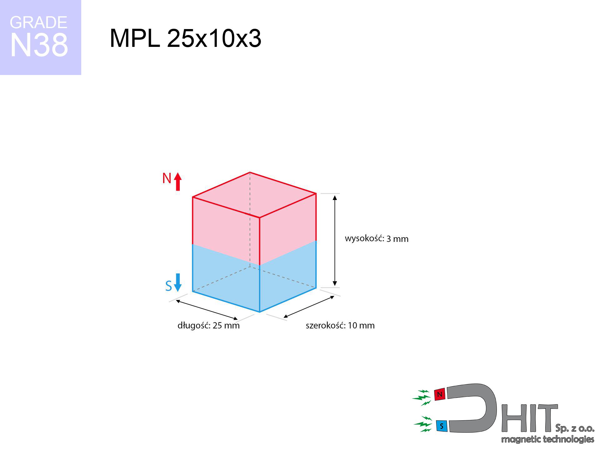
MPL 25x10x3 / N38 - lamellar magnet
lamellar magnet
Catalog no 020387
GTIN/EAN: 5906301811862
length
25 mm [±0,1 mm]
Width
10 mm [±0,1 mm]
Height
3 mm [±0,1 mm]
Weight
5.63 g
Magnetization Direction
↑ axial
Load capacity
4.14 kg / 40.56 N
Magnetic Induction
230.69 mT / 2307 Gs
Coating
[NiCuNi] Nickel
3.57 ZŁ with VAT / pcs + price for transport
2.90 ZŁ net + 23% VAT / pcs
bulk discounts:
Need more?
Contact us by phone
+48 888 99 98 98
if you prefer drop us a message by means of
form
the contact form page.
Specifications along with shape of a magnet can be tested with our
force calculator.
Orders placed before 14:00 will be shipped the same business day.
Physical properties - MPL 25x10x3 / N38 - lamellar magnet
Specification / characteristics - MPL 25x10x3 / N38 - lamellar magnet
| properties | values |
|---|---|
| Cat. no. | 020387 |
| GTIN/EAN | 5906301811862 |
| Production/Distribution | Dhit sp. z o.o. |
| Country of origin | Poland / China / Germany |
| Customs code | 85059029 |
| length | 25 mm [±0,1 mm] |
| Width | 10 mm [±0,1 mm] |
| Height | 3 mm [±0,1 mm] |
| Weight | 5.63 g |
| Magnetization Direction | ↑ axial |
| Load capacity ~ ? | 4.14 kg / 40.56 N |
| Magnetic Induction ~ ? | 230.69 mT / 2307 Gs |
| Coating | [NiCuNi] Nickel |
| Manufacturing Tolerance | ±0.1 mm |
Magnetic properties of material N38
| properties | values | units |
|---|---|---|
| remenance Br [min. - max.] ? | 12.2-12.6 | kGs |
| remenance Br [min. - max.] ? | 1220-1260 | mT |
| coercivity bHc ? | 10.8-11.5 | kOe |
| coercivity bHc ? | 860-915 | kA/m |
| actual internal force iHc | ≥ 12 | kOe |
| actual internal force iHc | ≥ 955 | kA/m |
| energy density [min. - max.] ? | 36-38 | BH max MGOe |
| energy density [min. - max.] ? | 287-303 | BH max KJ/m |
| max. temperature ? | ≤ 80 | °C |
Physical properties of sintered neodymium magnets Nd2Fe14B at 20°C
| properties | values | units |
|---|---|---|
| Vickers hardness | ≥550 | Hv |
| Density | ≥7.4 | g/cm3 |
| Curie Temperature TC | 312 - 380 | °C |
| Curie Temperature TF | 593 - 716 | °F |
| Specific resistance | 150 | μΩ⋅cm |
| Bending strength | 250 | MPa |
| Compressive strength | 1000~1100 | MPa |
| Thermal expansion parallel (∥) to orientation (M) | (3-4) x 10-6 | °C-1 |
| Thermal expansion perpendicular (⊥) to orientation (M) | -(1-3) x 10-6 | °C-1 |
| Young's modulus | 1.7 x 10⁴ | kg/mm² |
Engineering simulation of the product - data
These values represent the outcome of a engineering simulation. Results were calculated on models for the material Nd2Fe14B. Actual parameters might slightly differ. Use these data as a supplementary guide for designers.
Table 1: Static pull force (force vs distance) - power drop
MPL 25x10x3 / N38
| Distance (mm) | Induction (Gauss) / mT | Pull Force (kg/lbs/g/N) | Risk Status |
|---|---|---|---|
| 0 mm |
2306 Gs
230.6 mT
|
4.14 kg / 9.13 lbs
4140.0 g / 40.6 N
|
medium risk |
| 1 mm |
2050 Gs
205.0 mT
|
3.27 kg / 7.21 lbs
3272.4 g / 32.1 N
|
medium risk |
| 2 mm |
1752 Gs
175.2 mT
|
2.39 kg / 5.27 lbs
2388.9 g / 23.4 N
|
medium risk |
| 3 mm |
1463 Gs
146.3 mT
|
1.67 kg / 3.68 lbs
1667.1 g / 16.4 N
|
weak grip |
| 5 mm |
1000 Gs
100.0 mT
|
0.78 kg / 1.72 lbs
779.2 g / 7.6 N
|
weak grip |
| 10 mm |
416 Gs
41.6 mT
|
0.13 kg / 0.30 lbs
134.4 g / 1.3 N
|
weak grip |
| 15 mm |
200 Gs
20.0 mT
|
0.03 kg / 0.07 lbs
31.0 g / 0.3 N
|
weak grip |
| 20 mm |
108 Gs
10.8 mT
|
0.01 kg / 0.02 lbs
9.0 g / 0.1 N
|
weak grip |
| 30 mm |
40 Gs
4.0 mT
|
0.00 kg / 0.00 lbs
1.3 g / 0.0 N
|
weak grip |
| 50 mm |
10 Gs
1.0 mT
|
0.00 kg / 0.00 lbs
0.1 g / 0.0 N
|
weak grip |
Table 2: Sliding force (wall)
MPL 25x10x3 / N38
| Distance (mm) | Friction coefficient | Pull Force (kg/lbs/g/N) |
|---|---|---|
| 0 mm | Stal (~0.2) |
0.83 kg / 1.83 lbs
828.0 g / 8.1 N
|
| 1 mm | Stal (~0.2) |
0.65 kg / 1.44 lbs
654.0 g / 6.4 N
|
| 2 mm | Stal (~0.2) |
0.48 kg / 1.05 lbs
478.0 g / 4.7 N
|
| 3 mm | Stal (~0.2) |
0.33 kg / 0.74 lbs
334.0 g / 3.3 N
|
| 5 mm | Stal (~0.2) |
0.16 kg / 0.34 lbs
156.0 g / 1.5 N
|
| 10 mm | Stal (~0.2) |
0.03 kg / 0.06 lbs
26.0 g / 0.3 N
|
| 15 mm | Stal (~0.2) |
0.01 kg / 0.01 lbs
6.0 g / 0.1 N
|
| 20 mm | Stal (~0.2) |
0.00 kg / 0.00 lbs
2.0 g / 0.0 N
|
| 30 mm | Stal (~0.2) |
0.00 kg / 0.00 lbs
0.0 g / 0.0 N
|
| 50 mm | Stal (~0.2) |
0.00 kg / 0.00 lbs
0.0 g / 0.0 N
|
Table 3: Vertical assembly (shearing) - vertical pull
MPL 25x10x3 / N38
| Surface type | Friction coefficient / % Mocy | Max load (kg/lbs/g/N) |
|---|---|---|
| Raw steel |
µ = 0.3
30% Nominalnej Siły
|
1.24 kg / 2.74 lbs
1242.0 g / 12.2 N
|
| Painted steel (standard) |
µ = 0.2
20% Nominalnej Siły
|
0.83 kg / 1.83 lbs
828.0 g / 8.1 N
|
| Oily/slippery steel |
µ = 0.1
10% Nominalnej Siły
|
0.41 kg / 0.91 lbs
414.0 g / 4.1 N
|
| Magnet with anti-slip rubber |
µ = 0.5
50% Nominalnej Siły
|
2.07 kg / 4.56 lbs
2070.0 g / 20.3 N
|
Table 4: Material efficiency (saturation) - power losses
MPL 25x10x3 / N38
| Steel thickness (mm) | % power | Real pull force (kg/lbs/g/N) |
|---|---|---|
| 0.5 mm |
|
0.41 kg / 0.91 lbs
414.0 g / 4.1 N
|
| 1 mm |
|
1.04 kg / 2.28 lbs
1035.0 g / 10.2 N
|
| 2 mm |
|
2.07 kg / 4.56 lbs
2070.0 g / 20.3 N
|
| 3 mm |
|
3.10 kg / 6.85 lbs
3105.0 g / 30.5 N
|
| 5 mm |
|
4.14 kg / 9.13 lbs
4140.0 g / 40.6 N
|
| 10 mm |
|
4.14 kg / 9.13 lbs
4140.0 g / 40.6 N
|
| 11 mm |
|
4.14 kg / 9.13 lbs
4140.0 g / 40.6 N
|
| 12 mm |
|
4.14 kg / 9.13 lbs
4140.0 g / 40.6 N
|
Table 5: Thermal stability (stability) - power drop
MPL 25x10x3 / N38
| Ambient temp. (°C) | Power loss | Remaining pull (kg/lbs/g/N) | Status |
|---|---|---|---|
| 20 °C | 0.0% |
4.14 kg / 9.13 lbs
4140.0 g / 40.6 N
|
OK |
| 40 °C | -2.2% |
4.05 kg / 8.93 lbs
4048.9 g / 39.7 N
|
OK |
| 60 °C | -4.4% |
3.96 kg / 8.73 lbs
3957.8 g / 38.8 N
|
|
| 80 °C | -6.6% |
3.87 kg / 8.52 lbs
3866.8 g / 37.9 N
|
|
| 100 °C | -28.8% |
2.95 kg / 6.50 lbs
2947.7 g / 28.9 N
|
Table 6: Magnet-Magnet interaction (repulsion) - field range
MPL 25x10x3 / N38
| Gap (mm) | Attraction (kg/lbs) (N-S) | Sliding Force (kg/lbs/g/N) | Repulsion (kg/lbs) (N-N) |
|---|---|---|---|
| 0 mm |
8.20 kg / 18.07 lbs
3 767 Gs
|
1.23 kg / 2.71 lbs
1230 g / 12.1 N
|
N/A |
| 1 mm |
7.38 kg / 16.27 lbs
4 377 Gs
|
1.11 kg / 2.44 lbs
1107 g / 10.9 N
|
6.64 kg / 14.65 lbs
~0 Gs
|
| 2 mm |
6.48 kg / 14.28 lbs
4 101 Gs
|
0.97 kg / 2.14 lbs
972 g / 9.5 N
|
5.83 kg / 12.86 lbs
~0 Gs
|
| 3 mm |
5.58 kg / 12.30 lbs
3 805 Gs
|
0.84 kg / 1.84 lbs
837 g / 8.2 N
|
5.02 kg / 11.07 lbs
~0 Gs
|
| 5 mm |
3.97 kg / 8.74 lbs
3 208 Gs
|
0.59 kg / 1.31 lbs
595 g / 5.8 N
|
3.57 kg / 7.87 lbs
~0 Gs
|
| 10 mm |
1.54 kg / 3.40 lbs
2 001 Gs
|
0.23 kg / 0.51 lbs
231 g / 2.3 N
|
1.39 kg / 3.06 lbs
~0 Gs
|
| 20 mm |
0.27 kg / 0.59 lbs
831 Gs
|
0.04 kg / 0.09 lbs
40 g / 0.4 N
|
0.24 kg / 0.53 lbs
~0 Gs
|
| 50 mm |
0.01 kg / 0.01 lbs
127 Gs
|
0.00 kg / 0.00 lbs
1 g / 0.0 N
|
0.00 kg / 0.00 lbs
~0 Gs
|
| 60 mm |
0.00 kg / 0.01 lbs
80 Gs
|
0.00 kg / 0.00 lbs
0 g / 0.0 N
|
0.00 kg / 0.00 lbs
~0 Gs
|
| 70 mm |
0.00 kg / 0.00 lbs
54 Gs
|
0.00 kg / 0.00 lbs
0 g / 0.0 N
|
0.00 kg / 0.00 lbs
~0 Gs
|
| 80 mm |
0.00 kg / 0.00 lbs
38 Gs
|
0.00 kg / 0.00 lbs
0 g / 0.0 N
|
0.00 kg / 0.00 lbs
~0 Gs
|
| 90 mm |
0.00 kg / 0.00 lbs
27 Gs
|
0.00 kg / 0.00 lbs
0 g / 0.0 N
|
0.00 kg / 0.00 lbs
~0 Gs
|
| 100 mm |
0.00 kg / 0.00 lbs
20 Gs
|
0.00 kg / 0.00 lbs
0 g / 0.0 N
|
0.00 kg / 0.00 lbs
~0 Gs
|
Table 7: Protective zones (implants) - precautionary measures
MPL 25x10x3 / N38
| Object / Device | Limit (Gauss) / mT | Safe distance |
|---|---|---|
| Pacemaker | 5 Gs (0.5 mT) | 6.5 cm |
| Hearing aid | 10 Gs (1.0 mT) | 5.5 cm |
| Timepiece | 20 Gs (2.0 mT) | 4.0 cm |
| Mobile device | 40 Gs (4.0 mT) | 3.5 cm |
| Remote | 50 Gs (5.0 mT) | 3.0 cm |
| Payment card | 400 Gs (40.0 mT) | 1.5 cm |
| HDD hard drive | 600 Gs (60.0 mT) | 1.0 cm |
Table 8: Collisions (kinetic energy) - warning
MPL 25x10x3 / N38
| Start from (mm) | Speed (km/h) | Energy (J) | Predicted outcome |
|---|---|---|---|
| 10 mm |
27.90 km/h
(7.75 m/s)
|
0.17 J | |
| 30 mm |
47.38 km/h
(13.16 m/s)
|
0.49 J | |
| 50 mm |
61.15 km/h
(16.99 m/s)
|
0.81 J | |
| 100 mm |
86.48 km/h
(24.02 m/s)
|
1.62 J |
Table 9: Coating parameters (durability)
MPL 25x10x3 / N38
| Technical parameter | Value / Description |
|---|---|
| Coating type | [NiCuNi] Nickel |
| Layer structure | Nickel - Copper - Nickel |
| Layer thickness | 10-20 µm |
| Salt spray test (SST) ? | 24 h |
| Recommended environment | Indoors only (dry) |
Table 10: Construction data (Pc)
MPL 25x10x3 / N38
| Parameter | Value | SI Unit / Description |
|---|---|---|
| Magnetic Flux | 5 928 Mx | 59.3 µWb |
| Pc Coefficient | 0.25 | Low (Flat) |
Table 11: Hydrostatics and buoyancy
MPL 25x10x3 / N38
| Environment | Effective steel pull | Effect |
|---|---|---|
| Air (land) | 4.14 kg | Standard |
| Water (riverbed) |
4.74 kg
(+0.60 kg buoyancy gain)
|
+14.5% |
1. Sliding resistance
*Warning: On a vertical surface, the magnet holds only ~20% of its perpendicular strength.
2. Steel saturation
*Thin metal sheet (e.g. computer case) drastically reduces the holding force.
3. Heat tolerance
*For standard magnets, the safety limit is 80°C.
4. Demagnetization curve and operating point (B-H)
chart generated for the permeance coefficient Pc (Permeance Coefficient) = 0.25
This simulation demonstrates the magnetic stability of the selected magnet under specific geometric conditions. The solid red line represents the demagnetization curve (material potential), while the dashed blue line is the load line based on the magnet's geometry. The Pc (Permeance Coefficient), also known as the load line slope, is a dimensionless value that describes the relationship between the magnet's shape and its magnetic stability. The intersection of these two lines (the black dot) is the operating point — it determines the actual magnetic flux density generated by the magnet in this specific configuration. A higher Pc value means the magnet is more 'slender' (tall relative to its area), resulting in a higher operating point and better resistance to irreversible demagnetization caused by external fields or temperature. A value of 0.42 is relatively low (typical for flat magnets), meaning the operating point is closer to the 'knee' of the curve — caution is advised when operating at temperatures near the maximum limit to avoid strength loss.
Elemental analysis
| iron (Fe) | 64% – 68% |
| neodymium (Nd) | 29% – 32% |
| boron (B) | 1.1% – 1.2% |
| dysprosium (Dy) | 0.5% – 2.0% |
| coating (Ni-Cu-Ni) | < 0.05% |
Environmental data
| recyclability (EoL) | 100% |
| recycled raw materials | ~10% (pre-cons) |
| carbon footprint | low / zredukowany |
| waste code (EWC) | 16 02 16 |
View more offers


![SM 32x325 [2xM8] / N42 - magnetic separator](https://cdn3.dhit.pl/graphics/products/sm-32x325-2xm8-fog.jpg "SM 32x325 [2xM8] / N42 - magnetic separator")

Pros as well as cons of Nd2Fe14B magnets.
Benefits
- They do not lose magnetism, even after nearly 10 years – the decrease in power is only ~1% (based on measurements),
- They possess excellent resistance to magnetism drop as a result of opposing magnetic fields,
- In other words, due to the smooth surface of silver, the element becomes visually attractive,
- The surface of neodymium magnets generates a intense magnetic field – this is a distinguishing feature,
- Due to their durability and thermal resistance, neodymium magnets are capable of operate (depending on the form) even at high temperatures reaching 230°C or more...
- Possibility of exact shaping and adjusting to individual conditions,
- Huge importance in innovative solutions – they serve a role in magnetic memories, brushless drives, precision medical tools, as well as industrial machines.
- Compactness – despite small sizes they provide effective action, making them ideal for precision applications
Disadvantages
- At strong impacts they can crack, therefore we advise placing them in steel cases. A metal housing provides additional protection against damage and increases the magnet's durability.
- When exposed to high temperature, neodymium magnets suffer a drop in strength. Often, when the temperature exceeds 80°C, their power decreases (depending on the size and shape of the magnet). For those who need magnets for extreme conditions, we offer [AH] versions withstanding up to 230°C
- Magnets exposed to a humid environment can corrode. Therefore when using outdoors, we advise using waterproof magnets made of rubber, plastic or other material protecting against moisture
- Limited possibility of creating nuts in the magnet and complex shapes - preferred is a housing - magnetic holder.
- Potential hazard resulting from small fragments of magnets are risky, when accidentally swallowed, which gains importance in the aspect of protecting the youngest. Additionally, small components of these products are able to complicate diagnosis medical in case of swallowing.
- Higher cost of purchase is one of the disadvantages compared to ceramic magnets, especially in budget applications
Lifting parameters
Detachment force of the magnet in optimal conditions – what affects it?
- with the use of a sheet made of special test steel, guaranteeing full magnetic saturation
- possessing a thickness of at least 10 mm to avoid saturation
- with a surface free of scratches
- with total lack of distance (without coatings)
- under vertical force direction (90-degree angle)
- at room temperature
What influences lifting capacity in practice
- Gap (between the magnet and the metal), because even a microscopic clearance (e.g. 0.5 mm) can cause a reduction in force by up to 50% (this also applies to varnish, rust or dirt).
- Loading method – declared lifting capacity refers to detachment vertically. When attempting to slide, the magnet holds significantly lower power (often approx. 20-30% of maximum force).
- Metal thickness – thin material does not allow full use of the magnet. Part of the magnetic field penetrates through instead of generating force.
- Material type – ideal substrate is high-permeability steel. Stainless steels may have worse magnetic properties.
- Surface condition – smooth surfaces guarantee perfect abutment, which improves force. Uneven metal reduce efficiency.
- Thermal environment – heating the magnet causes a temporary drop of force. It is worth remembering the maximum operating temperature for a given model.
Lifting capacity testing was conducted on a smooth plate of optimal thickness, under perpendicular forces, in contrast under attempts to slide the magnet the holding force is lower. In addition, even a small distance between the magnet and the plate decreases the holding force.
Safety rules for work with NdFeB magnets
Life threat
Health Alert: Strong magnets can deactivate heart devices and defibrillators. Stay away if you have electronic implants.
Maximum temperature
Control the heat. Heating the magnet to high heat will ruin its magnetic structure and strength.
Impact on smartphones
Remember: rare earth magnets generate a field that interferes with sensitive sensors. Keep a safe distance from your mobile, device, and GPS.
Metal Allergy
Allergy Notice: The nickel-copper-nickel coating contains nickel. If redness appears, cease working with magnets and use protective gear.
Physical harm
Mind your fingers. Two powerful magnets will snap together instantly with a force of several hundred kilograms, crushing everything in their path. Be careful!
Magnetic media
Powerful magnetic fields can corrupt files on credit cards, hard drives, and other magnetic media. Maintain a gap of at least 10 cm.
Fire warning
Powder produced during cutting of magnets is self-igniting. Do not drill into magnets unless you are an expert.
Keep away from children
Only for adults. Small elements can be swallowed, leading to severe trauma. Store away from children and animals.
Safe operation
Before starting, read the rules. Uncontrolled attraction can destroy the magnet or injure your hand. Think ahead.
Shattering risk
Protect your eyes. Magnets can fracture upon violent connection, ejecting sharp fragments into the air. Eye protection is mandatory.
Tabela kosztu i czasu dostawy
Płatność przed wysyłką:

GLS kurier
Przesyłka będzie u Ciebie za 2-3 dni
14.99 ZŁ

InPost Paczkomaty 24/7
Przesyłka będzie u Ciebie za 1-2 dni
12.30 ZŁ
Płatność przy odbiorze (pobranie):
GLS kurier
Przesyłka będzie u Ciebie za 1-2 dni
23.00 ZŁ
Rate the product
Your rating