
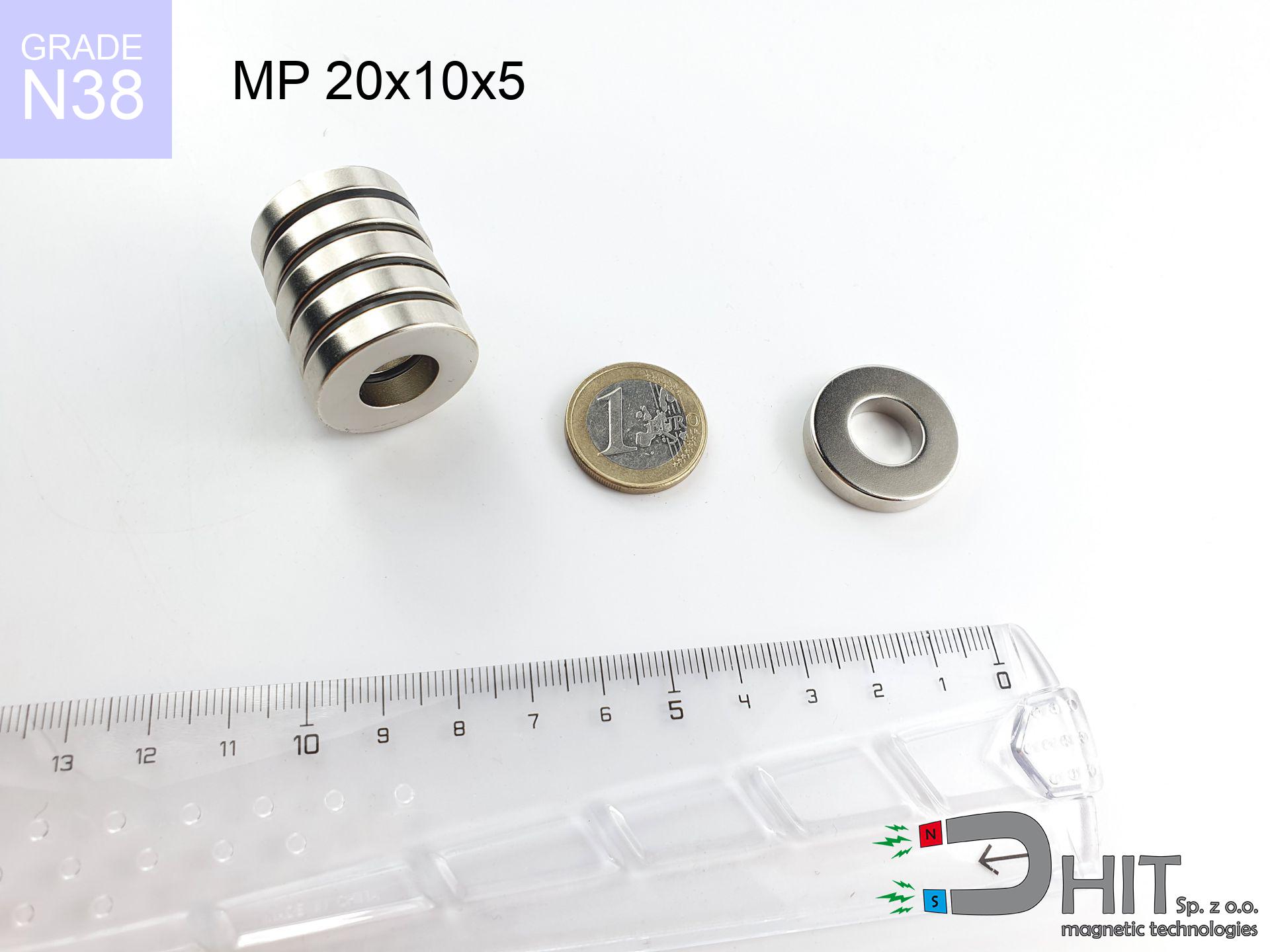
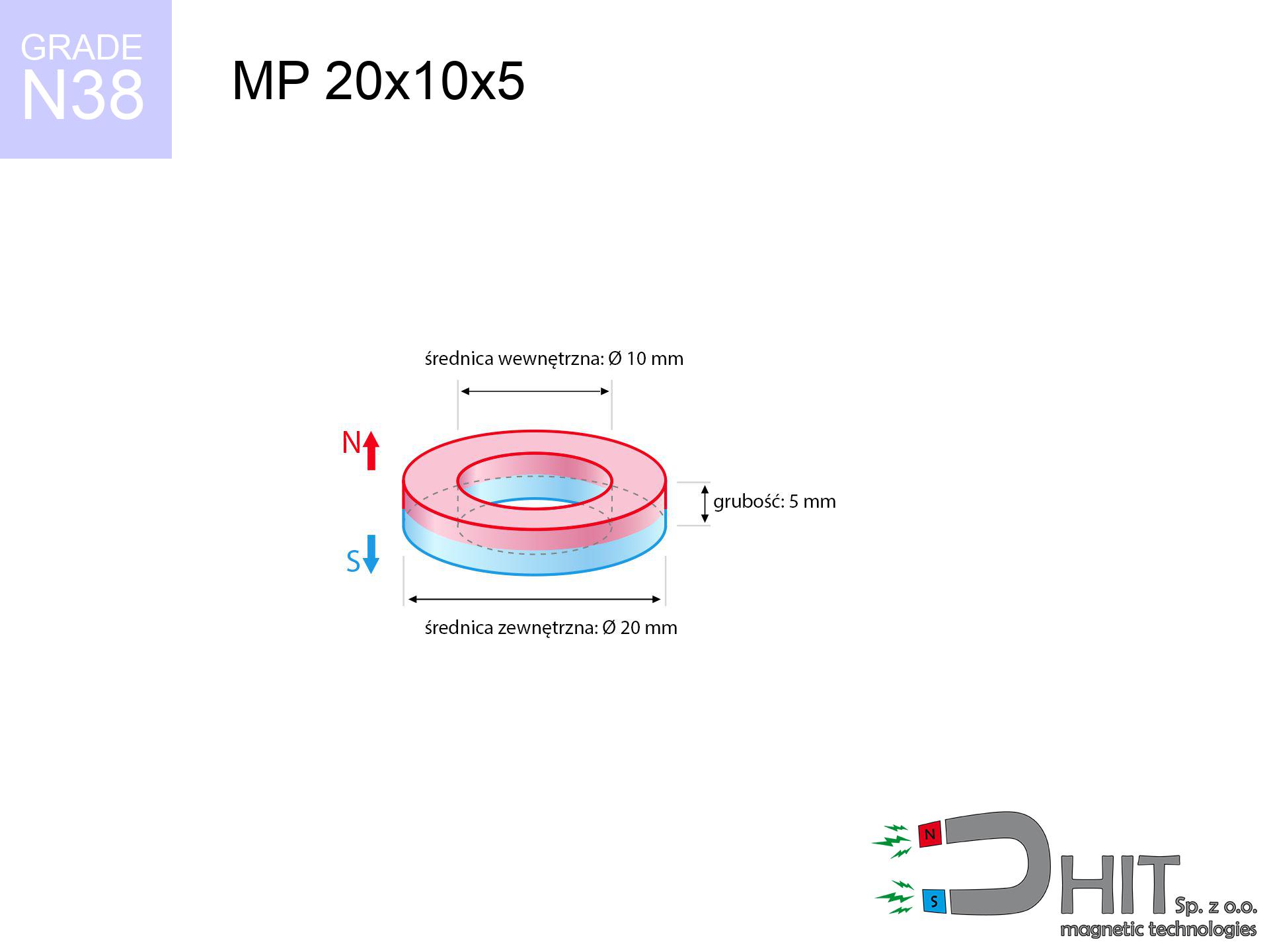
MP 20x10x5 / N38 - ring magnet
ring magnet
Catalog no 030184
GTIN/EAN: 5906301812012
Diameter
20 mm [±0,1 mm]
internal diameter Ø
10 mm [±0,1 mm]
Height
5 mm [±0,1 mm]
Weight
8.84 g
Magnetization Direction
↑ axial
Load capacity
5.20 kg / 50.97 N
Magnetic Induction
277.16 mT / 2772 Gs
Coating
[NiCuNi] Nickel
4.50 ZŁ with VAT / pcs + price for transport
3.66 ZŁ net + 23% VAT / pcs
bulk discounts:
Need more?
Contact us by phone
+48 22 499 98 98
otherwise contact us via
contact form
the contact section.
Strength and form of neodymium magnets can be calculated with our
online calculation tool.
Orders submitted before 14:00 will be dispatched today!
Technical specification of the product - MP 20x10x5 / N38 - ring magnet
Specification / characteristics - MP 20x10x5 / N38 - ring magnet
| properties | values |
|---|---|
| Cat. no. | 030184 |
| GTIN/EAN | 5906301812012 |
| Production/Distribution | Dhit sp. z o.o. |
| Country of origin | Poland / China / Germany |
| Customs code | 85059029 |
| Diameter | 20 mm [±0,1 mm] |
| internal diameter Ø | 10 mm [±0,1 mm] |
| Height | 5 mm [±0,1 mm] |
| Weight | 8.84 g |
| Magnetization Direction | ↑ axial |
| Load capacity ~ ? | 5.20 kg / 50.97 N |
| Magnetic Induction ~ ? | 277.16 mT / 2772 Gs |
| Coating | [NiCuNi] Nickel |
| Manufacturing Tolerance | ±0.1 mm |
Magnetic properties of material N38
| properties | values | units |
|---|---|---|
| remenance Br [min. - max.] ? | 12.2-12.6 | kGs |
| remenance Br [min. - max.] ? | 1220-1260 | mT |
| coercivity bHc ? | 10.8-11.5 | kOe |
| coercivity bHc ? | 860-915 | kA/m |
| actual internal force iHc | ≥ 12 | kOe |
| actual internal force iHc | ≥ 955 | kA/m |
| energy density [min. - max.] ? | 36-38 | BH max MGOe |
| energy density [min. - max.] ? | 287-303 | BH max KJ/m |
| max. temperature ? | ≤ 80 | °C |
Physical properties of sintered neodymium magnets Nd2Fe14B at 20°C
| properties | values | units |
|---|---|---|
| Vickers hardness | ≥550 | Hv |
| Density | ≥7.4 | g/cm3 |
| Curie Temperature TC | 312 - 380 | °C |
| Curie Temperature TF | 593 - 716 | °F |
| Specific resistance | 150 | μΩ⋅cm |
| Bending strength | 250 | MPa |
| Compressive strength | 1000~1100 | MPa |
| Thermal expansion parallel (∥) to orientation (M) | (3-4) x 10-6 | °C-1 |
| Thermal expansion perpendicular (⊥) to orientation (M) | -(1-3) x 10-6 | °C-1 |
| Young's modulus | 1.7 x 10⁴ | kg/mm² |
Engineering simulation of the product - report
Presented information are the result of a mathematical calculation. Results rely on algorithms for the material Nd2Fe14B. Operational parameters might slightly differ. Use these calculations as a preliminary roadmap during assembly planning.
Table 1: Static force (force vs distance) - characteristics
MP 20x10x5 / N38
| Distance (mm) | Induction (Gauss) / mT | Pull Force (kg/lbs/g/N) | Risk Status |
|---|---|---|---|
| 0 mm |
5917 Gs
591.7 mT
|
5.20 kg / 11.46 pounds
5200.0 g / 51.0 N
|
medium risk |
| 1 mm |
5321 Gs
532.1 mT
|
4.21 kg / 9.27 pounds
4205.9 g / 41.3 N
|
medium risk |
| 2 mm |
4736 Gs
473.6 mT
|
3.33 kg / 7.35 pounds
3332.2 g / 32.7 N
|
medium risk |
| 3 mm |
4184 Gs
418.4 mT
|
2.60 kg / 5.73 pounds
2600.0 g / 25.5 N
|
medium risk |
| 5 mm |
3216 Gs
321.6 mT
|
1.54 kg / 3.39 pounds
1536.2 g / 15.1 N
|
safe |
| 10 mm |
1650 Gs
165.0 mT
|
0.40 kg / 0.89 pounds
404.2 g / 4.0 N
|
safe |
| 15 mm |
907 Gs
90.7 mT
|
0.12 kg / 0.27 pounds
122.3 g / 1.2 N
|
safe |
| 20 mm |
544 Gs
54.4 mT
|
0.04 kg / 0.10 pounds
44.0 g / 0.4 N
|
safe |
| 30 mm |
240 Gs
24.0 mT
|
0.01 kg / 0.02 pounds
8.5 g / 0.1 N
|
safe |
| 50 mm |
75 Gs
7.5 mT
|
0.00 kg / 0.00 pounds
0.8 g / 0.0 N
|
safe |
Table 2: Vertical hold (wall)
MP 20x10x5 / N38
| Distance (mm) | Friction coefficient | Pull Force (kg/lbs/g/N) |
|---|---|---|
| 0 mm | Stal (~0.2) |
1.04 kg / 2.29 pounds
1040.0 g / 10.2 N
|
| 1 mm | Stal (~0.2) |
0.84 kg / 1.86 pounds
842.0 g / 8.3 N
|
| 2 mm | Stal (~0.2) |
0.67 kg / 1.47 pounds
666.0 g / 6.5 N
|
| 3 mm | Stal (~0.2) |
0.52 kg / 1.15 pounds
520.0 g / 5.1 N
|
| 5 mm | Stal (~0.2) |
0.31 kg / 0.68 pounds
308.0 g / 3.0 N
|
| 10 mm | Stal (~0.2) |
0.08 kg / 0.18 pounds
80.0 g / 0.8 N
|
| 15 mm | Stal (~0.2) |
0.02 kg / 0.05 pounds
24.0 g / 0.2 N
|
| 20 mm | Stal (~0.2) |
0.01 kg / 0.02 pounds
8.0 g / 0.1 N
|
| 30 mm | Stal (~0.2) |
0.00 kg / 0.00 pounds
2.0 g / 0.0 N
|
| 50 mm | Stal (~0.2) |
0.00 kg / 0.00 pounds
0.0 g / 0.0 N
|
Table 3: Vertical assembly (sliding) - behavior on slippery surfaces
MP 20x10x5 / N38
| Surface type | Friction coefficient / % Mocy | Max load (kg/lbs/g/N) |
|---|---|---|
| Raw steel |
µ = 0.3
30% Nominalnej Siły
|
1.56 kg / 3.44 pounds
1560.0 g / 15.3 N
|
| Painted steel (standard) |
µ = 0.2
20% Nominalnej Siły
|
1.04 kg / 2.29 pounds
1040.0 g / 10.2 N
|
| Oily/slippery steel |
µ = 0.1
10% Nominalnej Siły
|
0.52 kg / 1.15 pounds
520.0 g / 5.1 N
|
| Magnet with anti-slip rubber |
µ = 0.5
50% Nominalnej Siły
|
2.60 kg / 5.73 pounds
2600.0 g / 25.5 N
|
Table 4: Material efficiency (substrate influence) - power losses
MP 20x10x5 / N38
| Steel thickness (mm) | % power | Real pull force (kg/lbs/g/N) |
|---|---|---|
| 0.5 mm |
|
0.52 kg / 1.15 pounds
520.0 g / 5.1 N
|
| 1 mm |
|
1.30 kg / 2.87 pounds
1300.0 g / 12.8 N
|
| 2 mm |
|
2.60 kg / 5.73 pounds
2600.0 g / 25.5 N
|
| 3 mm |
|
3.90 kg / 8.60 pounds
3900.0 g / 38.3 N
|
| 5 mm |
|
5.20 kg / 11.46 pounds
5200.0 g / 51.0 N
|
| 10 mm |
|
5.20 kg / 11.46 pounds
5200.0 g / 51.0 N
|
| 11 mm |
|
5.20 kg / 11.46 pounds
5200.0 g / 51.0 N
|
| 12 mm |
|
5.20 kg / 11.46 pounds
5200.0 g / 51.0 N
|
Table 5: Thermal stability (stability) - resistance threshold
MP 20x10x5 / N38
| Ambient temp. (°C) | Power loss | Remaining pull (kg/lbs/g/N) | Status |
|---|---|---|---|
| 20 °C | 0.0% |
5.20 kg / 11.46 pounds
5200.0 g / 51.0 N
|
OK |
| 40 °C | -2.2% |
5.09 kg / 11.21 pounds
5085.6 g / 49.9 N
|
OK |
| 60 °C | -4.4% |
4.97 kg / 10.96 pounds
4971.2 g / 48.8 N
|
OK |
| 80 °C | -6.6% |
4.86 kg / 10.71 pounds
4856.8 g / 47.6 N
|
|
| 100 °C | -28.8% |
3.70 kg / 8.16 pounds
3702.4 g / 36.3 N
|
Table 6: Magnet-Magnet interaction (repulsion) - forces in the system
MP 20x10x5 / N38
| Gap (mm) | Attraction (kg/lbs) (N-S) | Shear Strength (kg/lbs/g/N) | Repulsion (kg/lbs) (N-N) |
|---|---|---|---|
| 0 mm |
54.03 kg / 119.11 pounds
6 121 Gs
|
8.10 kg / 17.87 pounds
8104 g / 79.5 N
|
N/A |
| 1 mm |
48.76 kg / 107.50 pounds
11 242 Gs
|
7.31 kg / 16.13 pounds
7314 g / 71.8 N
|
43.89 kg / 96.75 pounds
~0 Gs
|
| 2 mm |
43.70 kg / 96.34 pounds
10 642 Gs
|
6.55 kg / 14.45 pounds
6555 g / 64.3 N
|
39.33 kg / 86.71 pounds
~0 Gs
|
| 3 mm |
38.98 kg / 85.94 pounds
10 051 Gs
|
5.85 kg / 12.89 pounds
5847 g / 57.4 N
|
35.08 kg / 77.34 pounds
~0 Gs
|
| 5 mm |
30.63 kg / 67.54 pounds
8 910 Gs
|
4.60 kg / 10.13 pounds
4595 g / 45.1 N
|
27.57 kg / 60.78 pounds
~0 Gs
|
| 10 mm |
15.96 kg / 35.19 pounds
6 432 Gs
|
2.39 kg / 5.28 pounds
2394 g / 23.5 N
|
14.36 kg / 31.67 pounds
~0 Gs
|
| 20 mm |
4.20 kg / 9.26 pounds
3 299 Gs
|
0.63 kg / 1.39 pounds
630 g / 6.2 N
|
3.78 kg / 8.33 pounds
~0 Gs
|
| 50 mm |
0.19 kg / 0.42 pounds
702 Gs
|
0.03 kg / 0.06 pounds
29 g / 0.3 N
|
0.17 kg / 0.38 pounds
~0 Gs
|
| 60 mm |
0.09 kg / 0.20 pounds
480 Gs
|
0.01 kg / 0.03 pounds
13 g / 0.1 N
|
0.08 kg / 0.18 pounds
~0 Gs
|
| 70 mm |
0.05 kg / 0.10 pounds
342 Gs
|
0.01 kg / 0.01 pounds
7 g / 0.1 N
|
0.04 kg / 0.09 pounds
~0 Gs
|
| 80 mm |
0.02 kg / 0.05 pounds
253 Gs
|
0.00 kg / 0.01 pounds
4 g / 0.0 N
|
0.02 kg / 0.05 pounds
~0 Gs
|
| 90 mm |
0.01 kg / 0.03 pounds
193 Gs
|
0.00 kg / 0.00 pounds
2 g / 0.0 N
|
0.01 kg / 0.03 pounds
~0 Gs
|
| 100 mm |
0.01 kg / 0.02 pounds
150 Gs
|
0.00 kg / 0.00 pounds
1 g / 0.0 N
|
0.00 kg / 0.00 pounds
~0 Gs
|
Table 7: Safety (HSE) (electronics) - precautionary measures
MP 20x10x5 / N38
| Object / Device | Limit (Gauss) / mT | Safe distance |
|---|---|---|
| Pacemaker | 5 Gs (0.5 mT) | 14.5 cm |
| Hearing aid | 10 Gs (1.0 mT) | 11.5 cm |
| Mechanical watch | 20 Gs (2.0 mT) | 9.0 cm |
| Phone / Smartphone | 40 Gs (4.0 mT) | 6.5 cm |
| Car key | 50 Gs (5.0 mT) | 6.0 cm |
| Payment card | 400 Gs (40.0 mT) | 2.5 cm |
| HDD hard drive | 600 Gs (60.0 mT) | 2.0 cm |
Table 8: Dynamics (kinetic energy) - warning
MP 20x10x5 / N38
| Start from (mm) | Speed (km/h) | Energy (J) | Predicted outcome |
|---|---|---|---|
| 10 mm |
25.62 km/h
(7.12 m/s)
|
0.22 J | |
| 30 mm |
42.41 km/h
(11.78 m/s)
|
0.61 J | |
| 50 mm |
54.70 km/h
(15.19 m/s)
|
1.02 J | |
| 100 mm |
77.35 km/h
(21.49 m/s)
|
2.04 J |
Table 9: Surface protection spec
MP 20x10x5 / N38
| Technical parameter | Value / Description |
|---|---|
| Coating type | [NiCuNi] Nickel |
| Layer structure | Nickel - Copper - Nickel |
| Layer thickness | 10-20 µm |
| Salt spray test (SST) ? | 24 h |
| Recommended environment | Indoors only (dry) |
Table 10: Construction data (Flux)
MP 20x10x5 / N38
| Parameter | Value | SI Unit / Description |
|---|---|---|
| Magnetic Flux | 16 116 Mx | 161.2 µWb |
| Pc Coefficient | 1.13 | High (Stable) |
Table 11: Hydrostatics and buoyancy
MP 20x10x5 / N38
| Environment | Effective steel pull | Effect |
|---|---|---|
| Air (land) | 5.20 kg | Standard |
| Water (riverbed) |
5.95 kg
(+0.75 kg buoyancy gain)
|
+14.5% |
1. Shear force
*Warning: On a vertical wall, the magnet retains just ~20% of its perpendicular strength.
2. Plate thickness effect
*Thin metal sheet (e.g. 0.5mm PC case) significantly reduces the holding force.
3. Heat tolerance
*For standard magnets, the safety limit is 80°C.
4. Demagnetization curve and operating point (B-H)
chart generated for the permeance coefficient Pc (Permeance Coefficient) = 1.13
This simulation demonstrates the magnetic stability of the selected magnet under specific geometric conditions. The solid red line represents the demagnetization curve (material potential), while the dashed blue line is the load line based on the magnet's geometry. The Pc (Permeance Coefficient), also known as the load line slope, is a dimensionless value that describes the relationship between the magnet's shape and its magnetic stability. The intersection of these two lines (the black dot) is the operating point — it determines the actual magnetic flux density generated by the magnet in this specific configuration. A higher Pc value means the magnet is more 'slender' (tall relative to its area), resulting in a higher operating point and better resistance to irreversible demagnetization caused by external fields or temperature. A value of 0.42 is relatively low (typical for flat magnets), meaning the operating point is closer to the 'knee' of the curve — caution is advised when operating at temperatures near the maximum limit to avoid strength loss.
Chemical composition
| iron (Fe) | 64% – 68% |
| neodymium (Nd) | 29% – 32% |
| boron (B) | 1.1% – 1.2% |
| dysprosium (Dy) | 0.5% – 2.0% |
| coating (Ni-Cu-Ni) | < 0.05% |
Environmental data
| recyclability (EoL) | 100% |
| recycled raw materials | ~10% (pre-cons) |
| carbon footprint | low / zredukowany |
| waste code (EWC) | 16 02 16 |
Other products
![AM ucho [M10] - magnetic accessories](https://cdn3.dhit.pl/graphics/products/am-ucho-m10-tij.jpg "AM ucho [M10] - magnetic accessories")
![UMP 94x28 [3xM10] GW F300 GOLD Lina / N38 - search holder](https://cdn3.dhit.pl/graphics/products/ump-94x28-m10-gw-f300-+lina-kac.jpg "UMP 94x28 [3xM10] GW F300 GOLD Lina / N38 - search holder")


Advantages as well as disadvantages of Nd2Fe14B magnets.
Strengths
- They virtually do not lose strength, because even after 10 years the decline in efficiency is only ~1% (based on calculations),
- Magnets effectively protect themselves against demagnetization caused by ambient magnetic noise,
- In other words, due to the glossy layer of silver, the element gains visual value,
- They feature high magnetic induction at the operating surface, which affects their effectiveness,
- Due to their durability and thermal resistance, neodymium magnets can operate (depending on the shape) even at high temperatures reaching 230°C or more...
- Due to the ability of free forming and adaptation to unique solutions, magnetic components can be created in a broad palette of forms and dimensions, which amplifies use scope,
- Wide application in high-tech industry – they are used in hard drives, electric drive systems, precision medical tools, also other advanced devices.
- Compactness – despite small sizes they provide effective action, making them ideal for precision applications
Weaknesses
- They are prone to damage upon too strong impacts. To avoid cracks, it is worth securing magnets in special housings. Such protection not only protects the magnet but also increases its resistance to damage
- We warn that neodymium magnets can reduce their strength at high temperatures. To prevent this, we advise our specialized [AH] magnets, which work effectively even at 230°C.
- Magnets exposed to a humid environment can corrode. Therefore while using outdoors, we recommend using water-impermeable magnets made of rubber, plastic or other material resistant to moisture
- Limited ability of making nuts in the magnet and complicated forms - preferred is a housing - mounting mechanism.
- Potential hazard resulting from small fragments of magnets are risky, when accidentally swallowed, which becomes key in the aspect of protecting the youngest. It is also worth noting that small components of these products can complicate diagnosis medical after entering the body.
- High unit price – neodymium magnets have a higher price than other types of magnets (e.g. ferrite), which can limit application in large quantities
Holding force characteristics
Maximum lifting force for a neodymium magnet – what it depends on?
- using a plate made of mild steel, acting as a ideal flux conductor
- possessing a thickness of at least 10 mm to ensure full flux closure
- with a plane free of scratches
- without the slightest insulating layer between the magnet and steel
- during detachment in a direction perpendicular to the mounting surface
- in temp. approx. 20°C
Key elements affecting lifting force
- Gap (between the magnet and the plate), as even a very small distance (e.g. 0.5 mm) can cause a reduction in lifting capacity by up to 50% (this also applies to paint, corrosion or dirt).
- Angle of force application – maximum parameter is reached only during pulling at a 90° angle. The force required to slide of the magnet along the plate is standardly many times lower (approx. 1/5 of the lifting capacity).
- Plate thickness – too thin steel does not accept the full field, causing part of the power to be wasted into the air.
- Plate material – low-carbon steel attracts best. Higher carbon content reduce magnetic properties and lifting capacity.
- Surface condition – smooth surfaces guarantee perfect abutment, which improves force. Uneven metal reduce efficiency.
- Thermal factor – hot environment reduces magnetic field. Exceeding the limit temperature can permanently demagnetize the magnet.
Lifting capacity testing was conducted on plates with a smooth surface of optimal thickness, under perpendicular forces, however under attempts to slide the magnet the load capacity is reduced by as much as fivefold. Additionally, even a slight gap between the magnet’s surface and the plate decreases the load capacity.
Warnings
Keep away from children
Adult use only. Tiny parts pose a choking risk, leading to serious injuries. Store out of reach of kids and pets.
Magnets are brittle
Despite metallic appearance, the material is delicate and cannot withstand shocks. Do not hit, as the magnet may shatter into sharp, dangerous pieces.
Safe operation
Before use, read the rules. Sudden snapping can break the magnet or injure your hand. Think ahead.
ICD Warning
People with a ICD have to maintain an absolute distance from magnets. The magnetism can stop the functioning of the life-saving device.
Crushing risk
Protect your hands. Two powerful magnets will snap together immediately with a force of several hundred kilograms, destroying anything in their path. Exercise extreme caution!
Phone sensors
GPS units and mobile phones are highly sensitive to magnetism. Close proximity with a powerful NdFeB magnet can decalibrate the internal compass in your phone.
Metal Allergy
Warning for allergy sufferers: The nickel-copper-nickel coating consists of nickel. If redness happens, immediately stop working with magnets and use protective gear.
Threat to electronics
Avoid bringing magnets close to a wallet, laptop, or screen. The magnetism can irreversibly ruin these devices and wipe information from cards.
Dust is flammable
Machining of NdFeB material poses a fire risk. Magnetic powder reacts violently with oxygen and is difficult to extinguish.
Demagnetization risk
Control the heat. Heating the magnet to high heat will destroy its properties and strength.
Tabela kosztu i czasu dostawy
Płatność przed wysyłką:

GLS kurier
Przesyłka będzie u Ciebie za 2-3 dni
14.99 ZŁ

InPost Paczkomaty 24/7
Przesyłka będzie u Ciebie za 1-2 dni
12.30 ZŁ
Płatność przy odbiorze (pobranie):
GLS kurier
Przesyłka będzie u Ciebie za 1-2 dni
23.00 ZŁ
Rate the product
Your rating